Check patentability & draft patents in minutes with Patsnap Eureka AI!

Fuel atomizer and method for atomizing fuel

A technology for atomizing and atomizing fuel, which is applied in the field of atomizers and can solve problems such as mixing of fuel and air that hinder atomization

Active Publication Date: 2022-06-21
SKY FORTUNE STAR TECH LTD
View PDF10 Cites 0 Cited by
  • Summary
  • Abstract
  • Description
  • Claims
  • Application Information

AI Technical Summary

Problems solved by technology

Also, the problem is exacerbated by the high pressure in the engine's combustion chamber, which in a way prevents the atomized fuel from mixing well with the air

Method used


Image

  • Fuel atomizer and method for atomizing fuel
  • Fuel atomizer and method for atomizing fuel
  • Fuel atomizer and method for atomizing fuel

Examples


Embodiment Construction

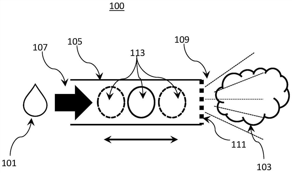
[0048] figure 1 A simplified side cross-sectional view of an embodiment of the present invention, which is a fuel atomizer 100 that converts liquefied fuel 101 into a fuel mist 103 . The fuel can be gasoline, petroleum, or any fuel fluid sufficient to be atomized into an atomized form.

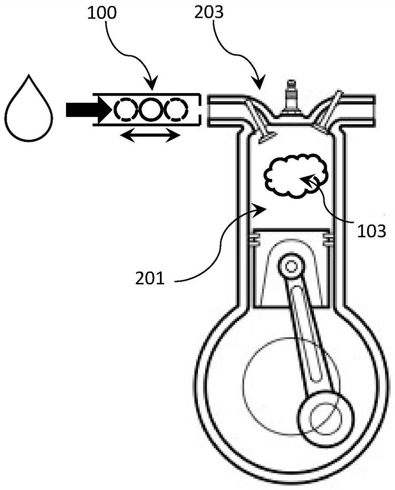
[0049] The atomizer 100 includes a conduit 105 for the passage of the fuel 101 . The outlet 109 of the duct 105 is connected to the combustion chamber of the engine, and the fuel 101 flows from the inlet 107 of the duct 105 to the outlet 109 of the duct 105 due to the suction generated by the combustion chamber. The outlet 109 of the conduit 105 is provided with a nozzle 111 that includes a small hole that causes the fuel 101 exiting the conduit 105 to be dispersed in a pressurized spray, effectively physically breaking the fuel 101 into a fine mist of fuel droplets 103. When the fuel 101 is present in the form of the mist 103, the surface area in contact with the air is increased. Therefo...


PUM


Abstract

A fuel atomizer (100) having conduits (105) for the passage of fuel (101). A body (113) is located in the conduit (105) for creating continuous and repetitive turbulent flow in the fuel (101). The turbulent flow of fuel exits the pipe (105) through the nozzle (111) as a fine mist spray (103). In some embodiments, the object (113) is a movable magnet (601) that is repelled by another magnet (701) at the exit (109) of the catheter (105). The flow of fuel (101) carries the movable magnet (601) to the outlet (109) of the pipe (105), while the other magnet (701) repels the movable magnet (601) backwards, causing repeated motion.

Description

technical field [0001] The present invention relates to an atomizer for combustion of fuels such as gasoline and petroleum for an engine. Background technique [0002] Engine fuel, such as gasoline, is provided in liquid form and stored in the vehicle's fuel tank. For fuel to be combusted in an engine, the fuel must first be physically broken down into a fuel mist through an atomization process. Gasoline mist is liquid, but it has been dispersed into fine droplets. This atomized fuel mixes well with air, which is critical for efficient combustion. In general, the smaller the droplet size and the finer the mist, the greater the surface area where the fuel can react directly with the air. [0003] There are two conventional methods of converting fuel into mist and introducing the mist into the combustion chamber of the engine. One method is to use a carburetor, the other is to use a fuel injector. [0004] The carburetor is just an air duct placed near a small outlet clos...

Claims


Application Information

Patent Timeline
Patent Type & Authority Patents(China)
IPC IPC(8): B05B1/34F02M29/00
CPCF02M27/045F02M2027/047F02M37/0052F02M31/16F23K5/08F23K2300/101F02M29/14F02M29/04B01J19/087B01J2219/0852F02F3/26F02M29/00F02M57/00F02M65/008F02M2700/4376
Inventor 邓经城
Owner SKY FORTUNE STAR TECH LTD
Features
  • R&D
  • Intellectual Property
  • Life Sciences
  • Materials
  • Tech Scout
  • Unparalleled Data Quality
  • Higher Quality Content
  • 60% Fewer Hallucinations
Learn More