Face masks for use in pressurized drug delivery systems

a technology of face mask and drug delivery system, which is applied in the field of masks, can solve the problems of increased drug deposition on the face, increased drug deposition and potential local side effects, and certain leakage areas

Inactive Publication Date: 2002-12-26
SMALDONE GERALD C
View PDF0 Cites 32 Cited by
  • Summary
  • Abstract
  • Description
  • Claims
  • Application Information

AI Technical Summary

Benefits of technology

[0075] One other advantage of the forming eye vents in a face mask that is intended for use with a pressurized drug delivery system, such as a nebulizer, is that existing face masks can easily be retrofitted by simply forming the eye vents in the region of the eyes using conventional techniques, such as a cutting process or any other type of process that is capable of removing or excising the face mask material along distinct lines to form the eye vents.
[0079] The foregoing written description is of a preferred embodiment and particular features of the present invention and is not restrictive of the many applications or the breadth of the present invention which is instead defined by the claims appended hereto and substantial equivalents thereof.

Problems solved by technology

Nebulizers readily pressurize the mask and deliver more drug but leaks around the face are enhanced, resulting in increased facial deposition of the drug.
Thus, leakage around the mask affects the performance of the particular device and in the case of nebulizers, leakage actually enhances the delivery of the drug; however, it is enhanced at the price of increased facial deposition and potentially local side effects.
For nebulizers, this produces certain leakage areas where the aerosolized drug can be discharged underneath the face mask and into the atmosphere.
Because of the design of face masks and their above-described placement over the face, leakage is universally present in the perinasal areas on either side of the nose.
In other words, aerosol is discharged underneath the face mask in these perinasal areas and flows directly towards the patient's eyes and unfortunately, many of the conventional masks are constructed in such a manner that the leaks that do occur are characterized as being high powered leaks (high kinetic energy) due to the high velocity that the fluid has as it flows underneath the mask and along the face directly into the eyes.
This may lead to several undesired side effects.
For example, deposition of the leaked aerosolized drug may be associated with direct trauma to the eyes and associated structures.
There is speculation that the risk of developing cataracts increases as a result of aerosolized drugs being directly deposited in the eyes of the patient.
At the very least, leakage of aerosolized drugs causes discomfort as the aerosol, traveling at a great velocity, is discharged underneath the face mask and deposits in the perinasal areas, including the eyes.
In addition, leaks of certain aerosols can cause dermatological problems in some patients due to an adverse reaction between facial skin and the aerosol.
Other undesirable conditions may result from having the aerosolized drug leaking and being deposited onto the face.
The disadvantages associated with conventional mask constructions are readily apparent by viewing FIGS. 1, 1a and 2. FIG. 1 is a front perspective view of a typical face mask 10 (that is commercially available from Laerdal Medical Corporation of Wappingers Falls, N.Y.).
The perinasal areas 15 are particularly prone to the formation of leaks and this results in the aerosolized drug being discharged directly into the eyes and the associated structures.
This results in some of the aerosolized drug being lost into the surrounding environment.
It has also been found that the degree of pressure applied to the mask in an attempt to improve the seal between the face mask and the face does not necessarily improve and may in fact worsen the leakage of the aerosolized drug in the perinasal areas when the patient inhales and draws the aerosolized drug into the face mask reservoir.
For example a caregiver pressing on the mask can seal leaks along the cheeks but promote leaks around the eyes.
The leakage of the aerosolized drug in the perinasal areas results in the aerosolized drug being discharged towards the eyes of the patient at high velocities due to the high kinetic energy of the fluid.
This is less than ideal as it may cause discomfort at the very least and may also lead to other medical complications due to the drug being discharged into the eyes of the patient.
Eye deposition is thus particularly a problem for those drug delivery systems that exert greater pressure on the face mask and / or maintain the face mask reservoir under pressure.
While face masks having been developed with venting mechanisms to cope with the pressurization requirements of a nebulizer or the like, these face masks still suffer from the disadvantage that they have constructions that not only permit aerosolized drug to be discharged in the perinasal areas but more importantly, the aerosolized drug is discharged at high velocities toward the eyes due to the imperfect interface between the face mask and the face.

Method used


Image

  • Face masks for use in pressurized drug delivery systems
  • Face masks for use in pressurized drug delivery systems
  • Face masks for use in pressurized drug delivery systems

Examples


first embodiment

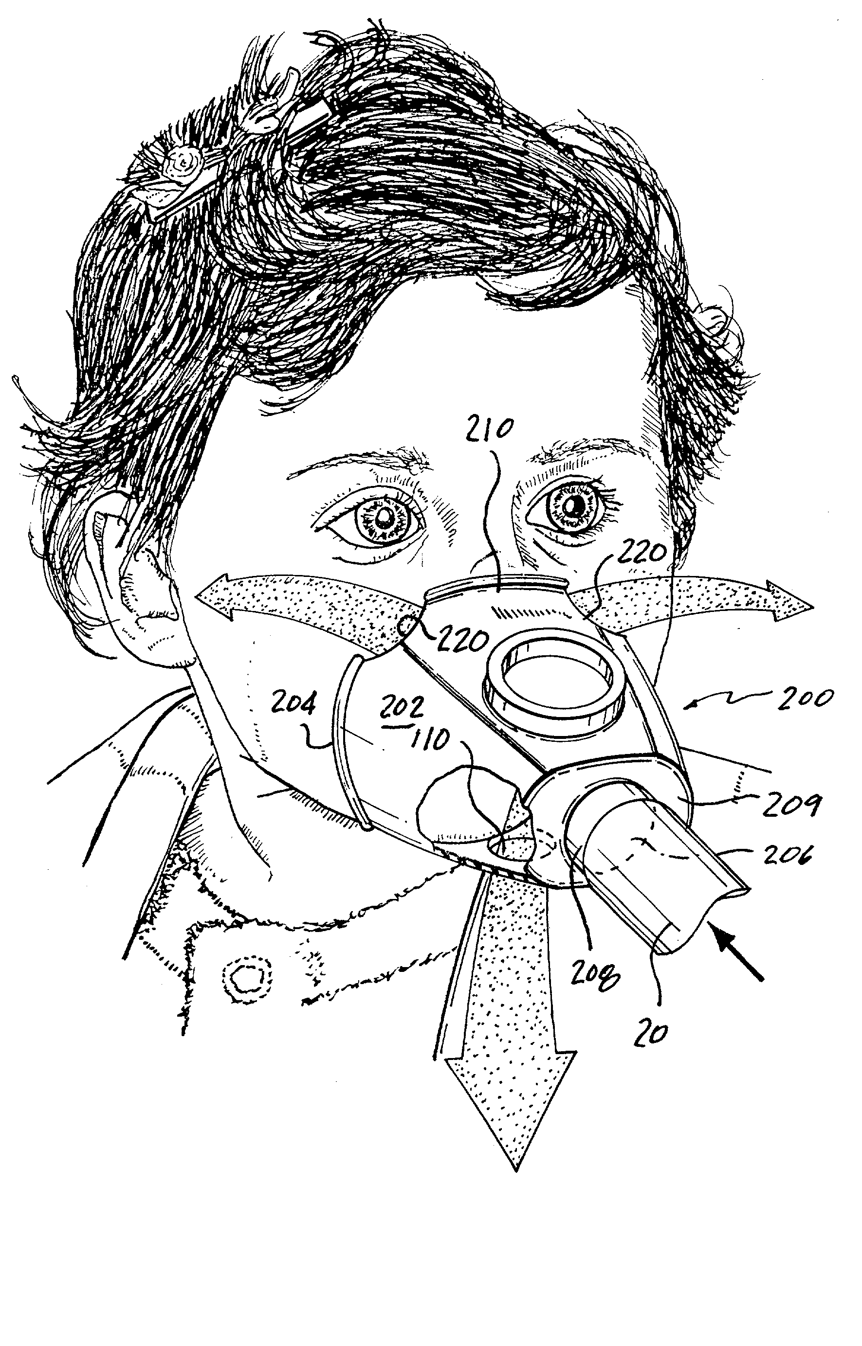
[0042] FIG. 3 is a front perspective view of an exemplary face mask 100 according to a For purposes of illustrating the benefits of the present invention, the face mask 100 is of a similar construction as the face mask 10 with one exception, as explained below. The face mask 100 thus includes a body 102 including a peripheral edge 104 which is intended to engage a face of a patient. The body 102 defines a face mask reservoir in which the patient's nasal openings and mouth are in communication. The body 102 is typically made of a flexible material, such as a thermoplastic, e.g., PVC material. The thickness of the material and cross-section varies to allow different parts of the exemplary face mask 100 to carry out their normal function. Thus, for example, the face mask 100 is generally of a relatively thin material with the peripheral sealing edge 104 also being of a thin flexible construction so that it can flexibly engage the face of the patient. The body 102 has a central opening...

second embodiment

[0045] Referring now to FIG. 4, an exemplary face mask 120 is illustrated. The exemplary face mask 120 has a body 122 similar to the body 12 of the face mask 10 of FIG. 1 with the exception that the face mask 120 has a pair of eye cut-outs or vents 130 formed by removing mask material along a peripheral edge 124 of the body 122. The eye vents 130 are formed on each side of a bridge section 126 of the face mask 120. The bridge section 126 is the mask section that generally seats against the bridge of the nose and interfaces with the cheeks of the patient adjacent the nose. The illustrated eye vents 130 are formed at the peripheral edge 124 and extend inwardly therefrom so as to remove mask material along the peripheral edge 124 under the patient's eyes. Each of the illustrated eye vents 130 has a semicircular shape; however, the precise shape of the eye vents 130 is not critical. For example, the eye vents 130 can alternatively be formed to have more of a rectangular shape in compar...

third embodiment

[0053] FIG. 5 shows a face mask 140 according to a The face mask 140 is very similar to the face mask 120 of FIG. 4 with the exception that the eye vents 150 have been enlarged in comparison to the eye vents 130 of FIG. 4. For example, the face mask 140 has an inner surface area of about 110 cm.sup.2 and the eye vents 150 occupy an area of about 10 cm.sup.2; however, these dimensions are merely exemplary and not limiting since the eye vents 150 can occupy an area less than 10 cm.sup.2 as well as an area greater than 10 cm.sup.2. Once again, the eye vents 150 are formed in the region of the eyes and the eye vents 150 can be formed in any number of different shapes. The shapes of the eye vents 150 in FIG. 5 are merely exemplary in nature. In this particular embodiment using this particular type of face mask, the eye vents can occupy From about 5 cm.sup.2 to about 11 cm.sup.2; however, these dimensions can be varied outside of this exemplary range. For this exemplary range, the eye ve...


PUM


Abstract

Face masks for use in pressurized drug delivery applications, such as aerosol drug delivery systems, and a method of reducing aerosol deposition in the region of the eyes are presented. The face masks according to the various embodiments disclosed herein contain features that reduce the inertia of the aerosolized drug in perinasal areas. This results in a reduction in the amount of aerosolized drug that is deposited in the region of the eyes by inertial impaction, while at the same time, the features are constructed to maintain the flow of the aerosolized drug into the face mask so that the aerosolized drug is effectively delivered to the respiratory system of the patient.

Description

[0001] This application claims the benefit of U.S. patent application Ser. No. 60 / 292,128, filed May 18, 2001, which is hereby incorporated by reference in its entirety.[0002] 1. Field of the Invention[0003] The present invention relates to a mask and more particularly, to a face mask for use in delivering an aerosolized drug or the like to a patient.[0004] 2. Description of Related Art[0005] Masks are commonly used in a wide range of applications and have widespread use in a number of medical settings. For example, masks are typically used in administering gases to a patient, e.g., an anesthetic agent, and more recently, masks have been increasingly used in drug delivery systems, including nebulizer drug delivery systems and metered dose inhalers using valved holding chambers (MDI / VHC). Nebulization is the application of a drug to a patient by means of an aerosol produced by a flow of gas. The aerosol and the drug are breathed in through the mask and are administered into the respi...

Claims


Application Information

Patent Timeline
Patent Type & Authority Applications(United States)
IPC IPC(8): A61M15/00A61M16/06
CPCA61M16/06A61M15/00
Inventor SMALDONE, GERALD C.
Owner SMALDONE GERALD C
Why Eureka
Try Eureka