
A double-sided art printing device

An art and printing technology, applied in printing, printing machines, general parts of printing machinery, etc., can solve problems such as inability to clean floating wool, affecting product quality, and insufficient cleaning

Active Publication Date: 2020-12-18
SHANGQIU NORMAL UNIVERSITY
View PDF10 Cites 0 Cited by
  • Summary
  • Abstract
  • Description
  • Claims
  • Application Information

AI Technical Summary

Problems solved by technology

[0002] With the development of society, modern consumers have higher and higher requirements for the personalization, fashion sense and artistic taste of fabrics, as well as for the color effect of fabrics. The use of double-sided printing can further improve the artistic effect of fabrics , the existing printing device cannot thoroughly clean the floating wool before printing, and all cotton fabrics will produce a large amount of floating wool. For products, after the printing is completed, the floating hair will be removed, which will cause whitening and affect the product quality. The existing floating hair cleaning device can only clean one area thoroughly, and the far side area may not be cleaned thoroughly due to insufficient suction, resulting in partial area cleaning. It is very thorough that the other parts have not been cleaned enough. If the suction power is increased a lot, the fabric may be sucked into the cleaning device, and it will consume more power. Some floating hairs cannot be cleaned thoroughly, which will leave hidden dangers for the next printing. At the same time, floating hair may also block the device, reduce production efficiency, and have a great impact on the health of workers in the workshop.

Method used


Image

  • A double-sided art printing device
  • A double-sided art printing device
  • A double-sided art printing device

Examples


Embodiment Construction

[0018] The present invention will be further described in detail below in conjunction with the accompanying drawings and examples. The following examples are explanations of the present invention and the present invention is not limited to the following examples.

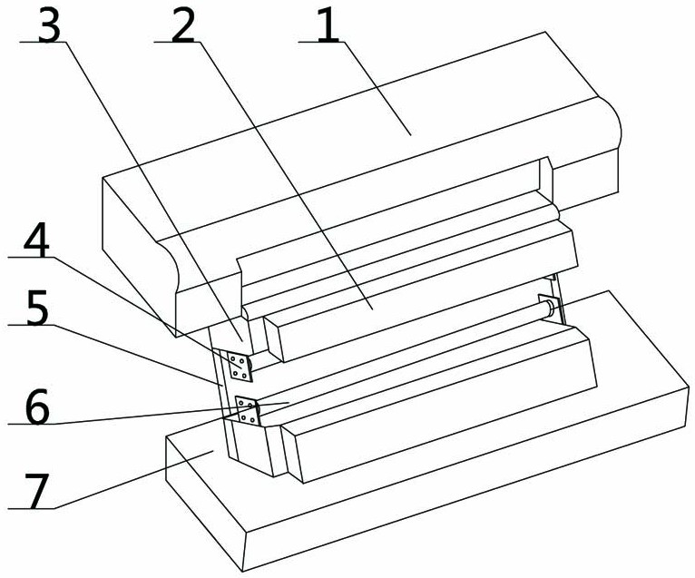
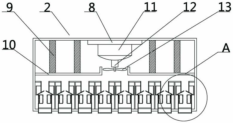
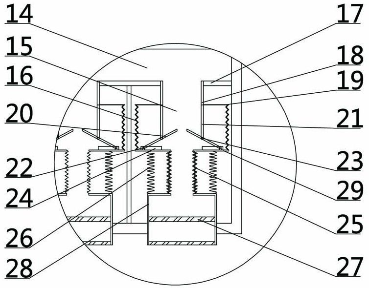
[0019] Such as Figure 1-4 As shown, a double-sided art printing device includes a device body 1, a base 7 is arranged at the bottom of the device body 1, a fixing frame 5 is arranged above the base 7, a workbench 3 is arranged symmetrically on the front side of the fixing frame 5, and the inside of the workbench 3 is fixed. Mounting plate 4, the first mounting plate 4 at the same height fixes the cloth cylinder 6, the front side of the workbench 3 fixes the hair suction device 2, the middle part of the inner top plate of the hair suction device 2 is provided with a second mounting plate 8, and the motor is fixed below the second mounting plate 8 11. A total of four filter screens 9 are arranged symmetrically on bot...


PUM


Abstract

The invention discloses a double-face fine art printing device. A device body is included. A workbench is arranged at the middle portion of the device body. A fluff suction device is fixed to the front side of the workbench. An installing plate is arranged at the middle portion below a top plate in the fluff suction device. A motor is fixed below the installing plate. Blades are arranged below themotor. A first fixing plate is arranged at the middle portion of the fluff suction device. A second fixing plate is arranged below the first fixing plate. A connecting pipe is arranged below the second fixing plate. A first telescopic pipe is arranged below the connecting pipe. A baffle is arranged in the first telescopic pipe. A rotation shaft is arranged at the middle portion of the baffle. A second telescopic pipe is arranged below the first telescopic pipe. A fixing spring is arranged on the outer side of the second telescopic pipe. A fixing box is arranged below the second telescopic pipe. In the printing device work process, the fluff suction device is used for conducting fluff removal on fabrics, then, printing is conducted, and the situations that floating fluff adheres to a printing mesh plate in the printing process, inferior-quality products are caused, the floating fluff possibly blocks the printing device, and the work efficiency is reduced are avoided.

Description

technical field [0001] The invention relates to the technical field of printing and dyeing equipment, in particular to a double-sided art printing device. Background technique [0002] With the development of society, modern consumers have higher and higher requirements for the personalization, fashion sense and artistic taste of fabrics, as well as for the color effect of fabrics. The use of double-sided printing can further improve the artistic effect of fabrics , the existing printing device cannot thoroughly clean the floating wool before printing, and all cotton fabrics will produce a large amount of floating wool. For products, after the printing is completed, the floating hair will be removed, which will cause whitening and affect the product quality. The existing floating hair cleaning device can only clean one area thoroughly, and the far side area may not be cleaned thoroughly due to insufficient suction, resulting in partial area cleaning. It is very thorough tha...

Claims


Application Information

Patent Timeline
Patent Type & Authority Patents(China)
IPC IPC(8): B41F23/00
CPCB41F23/002
Inventor 余航孟星星
Owner SHANGQIU NORMAL UNIVERSITY
Learn More