
Double-body combined wire drawing die with replaceable die holes and using method thereof

A combination of wire drawing die technology, applied in the direction of wire drawing dies, etc., can solve problems such as reducing wire drawing efficiency, delaying working hours, and reducing factory benefits, and achieves the effects of increasing factory revenue, improving production efficiency, and realizing controllability

Inactive Publication Date: 2021-03-02
天长市金浩日用品有限公司
View PDF0 Cites 0 Cited by
  • Summary
  • Abstract
  • Description
  • Claims
  • Application Information

AI Technical Summary

Problems solved by technology

[0003] However, the wire drawing dies in general factories need to be disassembled and replaced to adjust the size of the die hole. The operation is very cumbersome, so the convenience of accurate replacement is very poor. It often takes a lot of working time to replace a die hole, which greatly reduces the wire drawing. efficiency, thereby reducing the benefit of the plant

Method used


Image

  • Double-body combined wire drawing die with replaceable die holes and using method thereof
  • Double-body combined wire drawing die with replaceable die holes and using method thereof
  • Double-body combined wire drawing die with replaceable die holes and using method thereof

Examples


Embodiment 1

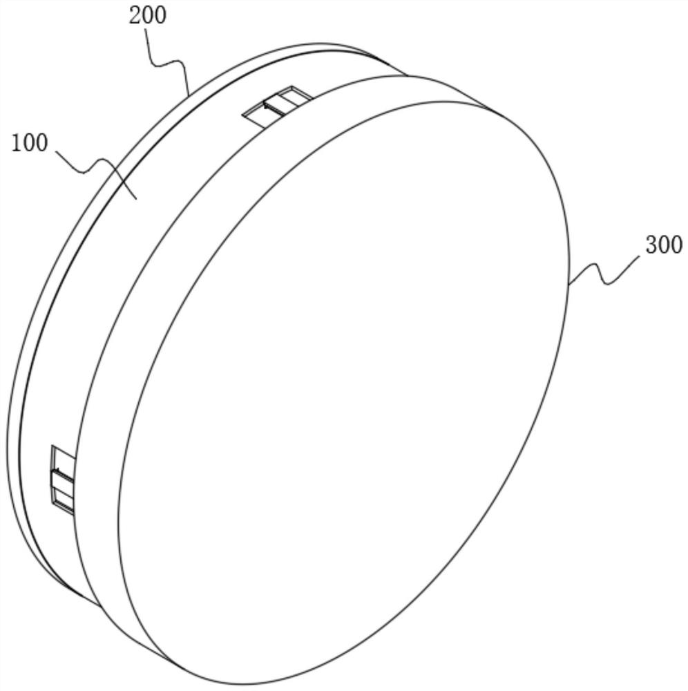
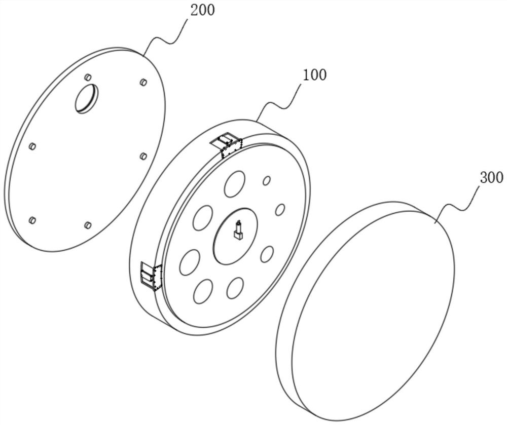
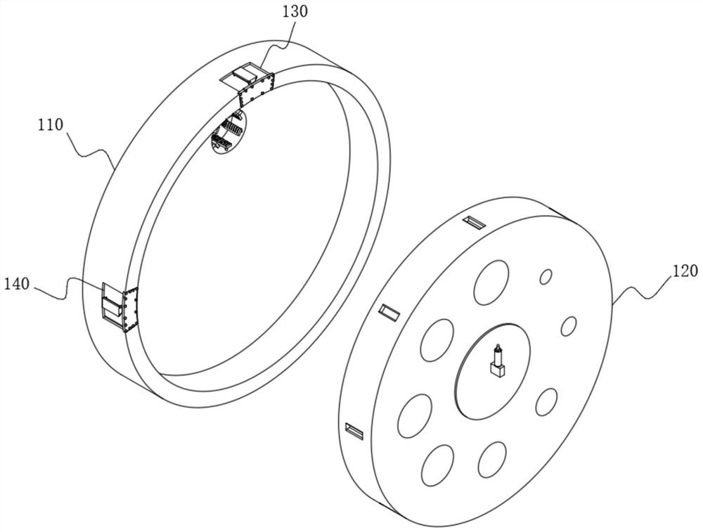
[0083] see Figure 1-Figure 13 As shown, one of the purposes of this embodiment is to provide a two-body combined wire drawing die with replaceable die holes, including a film changing hole mechanism 100, and the film changing hole mechanism 100 includes a back cover 110, and the inside of the back cover 110 is opened There is a "circular" groove opening forward, and a positioning hole 111 is opened on the rear side of the rear cover 110 near the top. The front cover 120 is arranged on the front side of the rear cover 110. The front cover 120 includes a front cover body 121, The front cover body 121 is rotationally connected with the "circular" groove of the back cover 110, and a plurality of die holes 1211 are ring-shaped around the front side wall of the front cover body 121. The inner wall of the die hole 1211 adopts natural diamond as a raw material. It has strong wear resistance, thereby prolonging the service life of the die hole 1211. The radius of the die hole 1211 gra...

Embodiment 2

[0105] In order to control the two-way rotation of 121 so that it can rotate clockwise in both directions and improve the rotation selectivity of the front cover body 121, please refer to image 3 , Figure 4 , Figure 8 , Figure 14 , Figure 15 with Figure 16 As shown, the right side of the rear cover 110 is provided with a unidirectional and bidirectional control device 140, the unidirectional and bidirectional control device 140 includes a control connection block 141, the control connection block 141 is fixedly connected with the rear cover 110, and the right side of the control connection block 141 is movably connected with a control Plate 143, so the bottom surface of the control plate 143 is an inclined surface, and the bottom surface of the control plate 143 is engaged with the insertion groove 1212. The right end of the control plate 143 is fixedly connected with a control plate 144, and the left side of the control plate 144 is provided with a control plate 143....


PUM


Abstract

The invention relates to a double-body combined wire drawing die with replaceable die holes and a using method thereof. The double-body combined wire drawing die comprises a die hole replacing mechanism, wherein the die hole replacing mechanism comprises a rear cover; a circular groove with a forward opening is formed in the rear cover; a positioning hole is formed in the position, close to the top, of the rear side of the rear cover; a front cover is arranged on the front side of the rear cover; the front cover comprises a front cover body; and the front cover body is rotationally connected with the circular groove of the rear cover. According to the double-body combined wire drawing die, the front cover body is fixed through clamping force generated by clamping fit of a limiting plate and an inserting groove, so that the front cover body is prevented from rotating during wire drawing; and in addition, the bidirectional wedge-shaped surface at the bottom of the limiting plate can realize bidirectional rotation of the front cover body, so that the problem of die hole conversion convenience is solved, the production efficiency is improved, and the factory income is increased.

Description

technical field [0001] The invention relates to the technical field of wire drawing dies, in particular to a two-body combined wire drawing die with replaceable die holes and a method for using the same. Background technique [0002] Usually refers to various dies for drawing metal wires, as well as drawing dies for drawing optical fibers. All drawing dies have holes of a certain shape, such as round, square, octagonal or other special shapes. When the metal is pulled through the die hole The size gets smaller and even the shape changes. [0003] However, the wire drawing dies in general factories need to be disassembled and replaced to adjust the size of the die hole. The operation is very cumbersome, so the convenience of accurate replacement is very poor. It often takes a lot of working time to replace a die with a die hole, which greatly reduces the wire drawing. efficiency, thereby reducing the benefit of the factory. Contents of the invention [0004] The object of...

Claims


Application Information

Patent Timeline
Patent Type & Authority Applications(China)
IPC IPC(8): B21C3/02B21C9/00
CPCB21C3/02B21C9/00
Inventor 张元山
Owner 天长市金浩日用品有限公司
Learn More