Electric push rod

An electric push rod and screw technology, which is applied in the direction of electric components, electrical components, electromechanical devices, etc., can solve the problems of disappearance, reduced life of electric push rods, loss of lubrication and cooling effects, etc., to ensure service life and not easy to consume Effect

Active Publication Date: 2019-12-17
绍兴市上虞荣达实业有限公司
View PDF5 Cites 4 Cited by
  • Summary
  • Abstract
  • Description
  • Claims
  • Application Information

AI Technical Summary

Problems solved by technology

[0005] But this kind of lubrication method, after long-term use, the lubricating oil on the thread surface of the screw and the nut will be reduced or even disappear due to the downflow or deterioration of the lubricating oil, thus losing the lubrication and cooling effect, and reducing the life of the electric push rod

Method used


Image

  • Electric push rod
  • Electric push rod
  • Electric push rod

Examples


Embodiment Construction

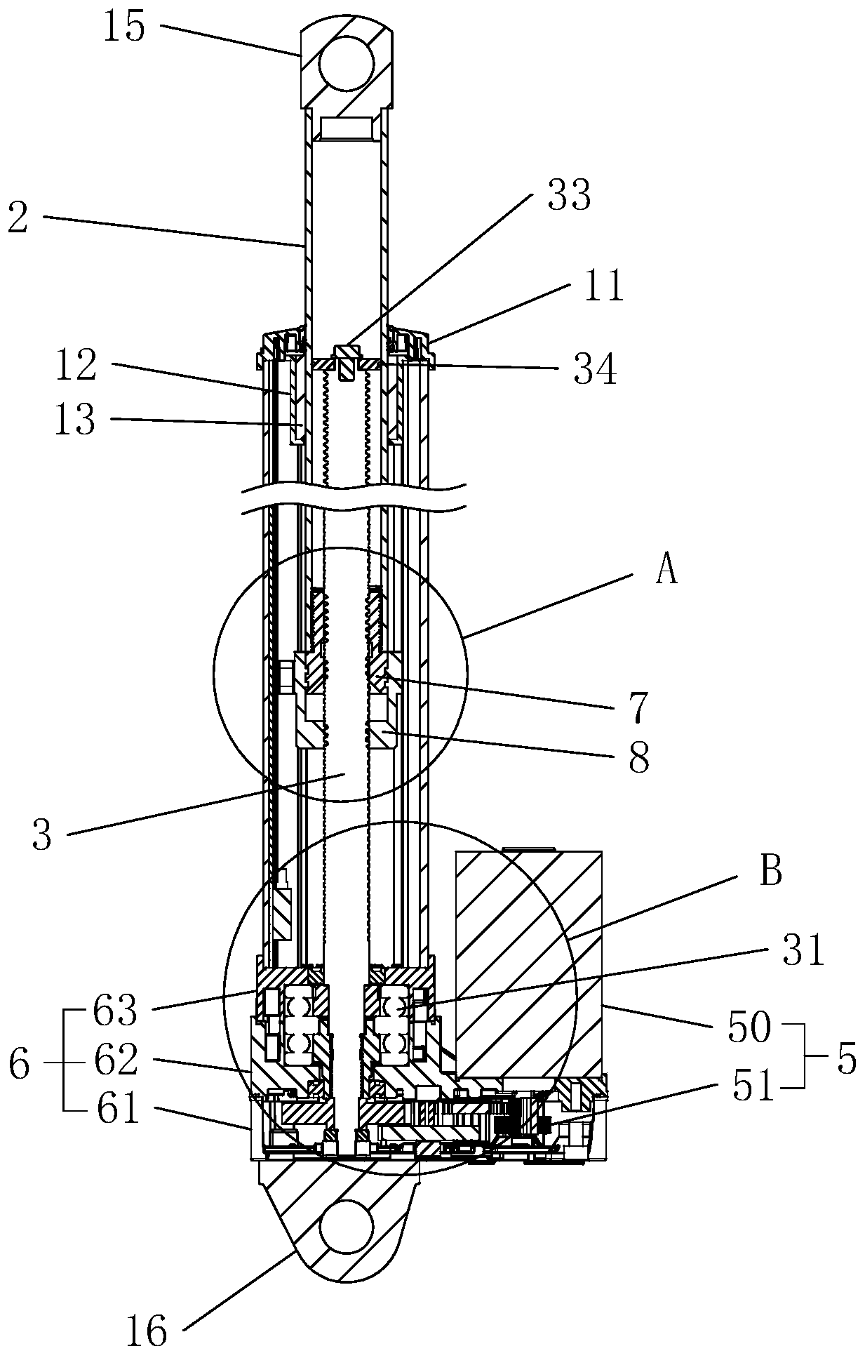
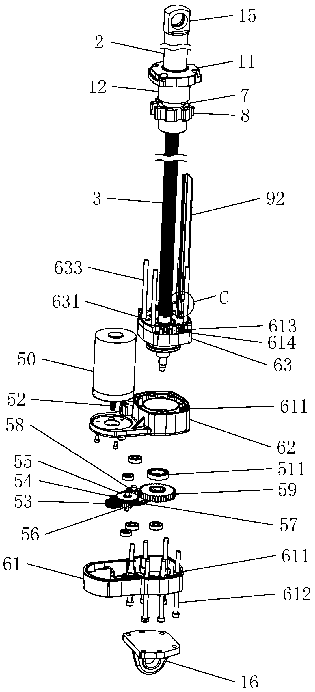
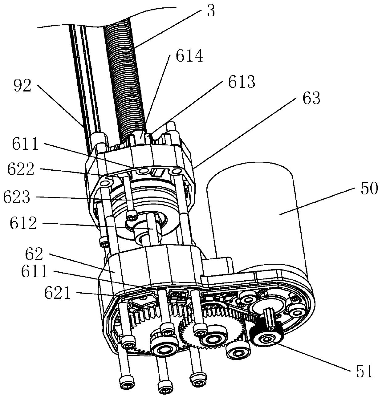
[0041] An electric push rod, such as figure 1 As shown, it includes a base 6, an outer tube 1, an inner tube 2, a screw rod 3, a nut 4, a driver 5 and an end cover 11. The base 6 includes an upper cover 62, a lower cover 61, and a special-shaped tube seat 63. One end of the outer tube 1 is connected to On the special-shaped pipe seat 63, the other end is fixedly connected with the end cap 11, and the end cap 11 is provided with an end cap hole for the inner tube 2 to pass through.

[0042] The end face of the end cover 11 facing the nut 4 is provided with a guide sleeve 12, the inner wall of the guide sleeve 12 is provided with a wear-resistant sleeve 13, the wear-resistant sleeve 13 is sleeved outside the inner tube 2 and fits with the outer wall of the inner tube 2, the wear-resistant sleeve 13 The material is POM plastic.

[0043] Such as figure 1 and figure 2 As shown, the end face of the lower cover 61 facing away from the upper cover 62 is fixedly connected with the ...


PUM


Abstract

The invention relates to the field of electric telescopic tools, and discloses an electric push rod. The rod comprises an outer tube, an inner tube, a screw, nuts and a driving piece, wherein the twoends of the outer tube are correspondingly provided with a base and an end cover, the screw is arranged in the outer tube, the two ends of the screw are rotationally connected with the base and the nuts correspondingly, the inner tube is coaxial with the screw, one end of the inner tube penetrates into the outer tube from the end cover and is arranged outside the screw in a sleeve mode, the nuts are arranged on the inner tube, the inner tube and the outer tube are in clamped connection in the rotating direction, the driving piece is used for driving the screw to rotate, the nuts comprise a main nut and an auxiliary nut, the auxiliary nut is provided with an inserting hole, the end part, facing the auxiliary nut, of the main nut is inserted into the inserting hole, a gap is reserved betweenthe end surface and the bottom surface of the inserting hole to form an oil storage cavity, the end surface, away from the main nut, of the auxiliary nut is provided with a communicating hole, the inner wall of the communicating hole is provided with an inner thread, the screw is inserted into the communicating hole and is in threaded connection with the main nut, and the screw is in threaded connection and is tightly matched with the internal thread. The rod has the advantages of good lubrication cooling effect and long service life.

Description

technical field [0001] The invention belongs to the field of electric telescopic tools, in particular to an electric push rod. Background technique [0002] Electric push rods, also known as push rod motors, electric cylinders and linear actuators. The electric push rod is an electric drive device that converts the rotary motion of the motor into the linear reciprocating motion of the push rod. It can be used as an execution machine in various simple or complex technological processes to realize remote control, centralized control or automatic control. [0003] The existing electric push rod includes a base, an outer tube, an inner tube, a screw, a nut and a driving part. The screw is rotatably connected to the base. The nut is set on the end of the inner tube facing the base and is threadedly connected with the screw. The inner tube and the outer tube are clamped in the direction of rotation along the axis. The driving part is set on the base and connected with the screw ...

Claims


Application Information

Patent Timeline
Patent Type & Authority Applications(China)
IPC IPC(8): F16H57/04F16H25/20F16H25/24H02K7/116
CPCF16H25/20F16H25/24F16H57/0427F16H57/0497F16H2025/2062F16H2025/2081H02K7/116
Inventor 叶伟青
Owner 绍兴市上虞荣达实业有限公司
Why Eureka
Try Eureka