Stereoscopic motion photographic equipment bracket

A photographic equipment and movement technology, which is applied in the direction of machines/supports, instruments, supporting machines, etc., can solve the problems of easy derailment, unstable connection of slide rails, difficulty in ensuring the lifting function of equipment, etc., and achieve a wide range of applications.

Active Publication Date: 2019-12-17
梅州市神牛摄影器材有限公司
View PDF6 Cites 4 Cited by
  • Summary
  • Abstract
  • Description
  • Claims
  • Application Information

AI Technical Summary

Problems solved by technology

[0004] However, the stability of the camera connection base of this device is not good, and its lifting structure is realized by two sets of electric cylinders. When one set of electric cylinders fails, it is difficult to ensure that the lifting function of the equipment can be realized smoothly, and the connection of the slide rails The method is not stable, and derailment is prone to occur during high-speed movement. In addition, the structure cannot automatically adjust the angle in the horizontal direction during shooting. It is necessary to provide a better anti-shake and shock absorption, and a stable structure with a wider range of applications. equipment

Method used


Image

  • Stereoscopic motion photographic equipment bracket
  • Stereoscopic motion photographic equipment bracket
  • Stereoscopic motion photographic equipment bracket

Examples


Embodiment Construction

[0052] The technical solutions of the present invention will be further described below in conjunction with the accompanying drawings and through specific implementation methods.

[0053] Wherein, the accompanying drawings are only for illustrative purposes, showing only schematic diagrams, rather than physical drawings, and should not be construed as limitations on this patent; in order to better illustrate the embodiments of the present invention, some parts of the accompanying drawings will be omitted, Enlargement or reduction does not represent the size of the actual product; for those skilled in the art, it is understandable that certain known structures and their descriptions in the drawings may be omitted.

[0054] In the drawings of the embodiments of the present invention, the same or similar symbols correspond to the same or similar components; , "inner", "outer" and other indicated orientations or positional relationships are based on the orientations or positional ...


PUM


Abstract

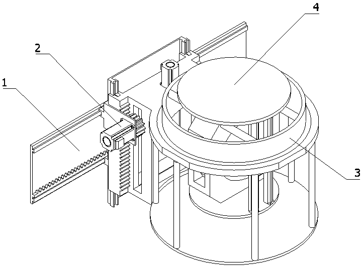
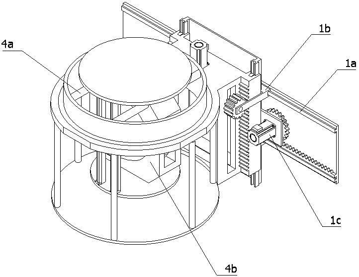
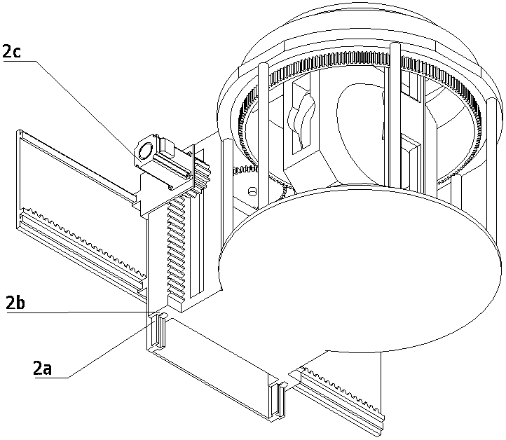
The invention relates to the field of photographic equipment, in particular to a stereoscopic motion photographic equipment bracket. The stereoscopic motion photographic equipment bracket comprises ahorizontal moving mechanism, a lifting mechanism, a rotating mechanism, a stabilizing mechanism and a controller; the horizontal moving mechanism is fixed to the side wall of a machine frame; the lifting mechanism is slidably installed on the horizontal moving mechanism; the rotating mechanism is fixed to the lifting mechanism; the stabilizing mechanism is fixedly installed on the rotating mechanism; and the horizontal moving mechanism, the lifting mechanism and the rotating mechanism are electrically connected with the controller. The stereoscopic motion photographic equipment bracket meets the anti-shake vibration requirements of photographic equipment during shooting, position adjusting of a camera in all the directions is achieved, the camera can conduct shooting at all angles in the horizontal direction, and the application range is wide.

Description

technical field [0001] The invention relates to the field of photography equipment, in particular to a three-dimensional sports photography equipment bracket. Background technique [0002] Sports photography refers to the continuous movement of the camera when shooting a shot. It means shooting by moving the camera position, or changing the optical axis of the lens, or changing the focal length of the lens in one shot. The pictures captured by this shooting method are called moving pictures. Such as: push lens, pull lens, pan lens, shift lens, follow lens, lift lens and comprehensive motion lens formed by push, pull, shake, move, follow, lift camera and comprehensive motion camera. There are three kinds of brackets used in traditional sports photography. One is held by people or carried on the shoulder. Although the rocker arm is relatively labor-saving, the equipment is large and difficult to move. The third type is commonly used in track and field stadiums. The photogra...

Claims


Application Information

Patent Timeline
Patent Type & Authority Applications(China)
IPC IPC(8): F16M11/04F16M11/06F16M11/18G03B17/56
CPCF16M11/045F16M11/046F16M11/06F16M11/18G03B17/56
Inventor 温涌君刘亮玲
Owner 梅州市神牛摄影器材有限公司
Why Eureka
Try Eureka