
Mobile terminal and antenna switching method

A technology for terminal antennas and mobile terminals, which is applied in the directions of antennas, antenna couplings, antenna arrays, etc., which can solve the problems of poor antenna isolation and influence on received signal strength, and achieve improved antenna isolation and weakened received signals , Improve the effect of user experience

Pending Publication Date: 2019-12-17
BLACKSHARK TECH NANCHANG CO LTD
View PDF5 Cites 6 Cited by
  • Summary
  • Abstract
  • Description
  • Claims
  • Application Information

AI Technical Summary

Problems solved by technology

[0005] In view of the above situation, it is necessary to provide a mobile terminal and an antenna switching method for the problem that increasing the number of mobile terminal antennas in the prior art leads to poor isolation between antennas, and when the antenna is held by the hand and affects the received signal strength

Method used


Image

  • Mobile terminal and antenna switching method
  • Mobile terminal and antenna switching method
  • Mobile terminal and antenna switching method

Examples


Embodiment Construction

[0038] In order to facilitate the understanding of the present invention, the present invention will be described more fully below with reference to the associated drawings. Embodiments of the invention are shown in the accompanying drawings. However, the present invention can be embodied in many different forms and is not limited to the embodiments described herein. On the contrary, the purpose of providing the embodiments is to make the disclosure of the present invention more thorough and comprehensive.

[0039] It should be noted that when an element is referred to as being “fixed on” another element, it may be directly on the other element or there may be an intervening element. When an element is referred to as being "connected to" another element, it can be directly connected to the other element or intervening elements may also be present. The terms "vertical," "horizontal," "left," "right," and similar expressions are used herein for purposes of illustration only. ...


PUM


Abstract

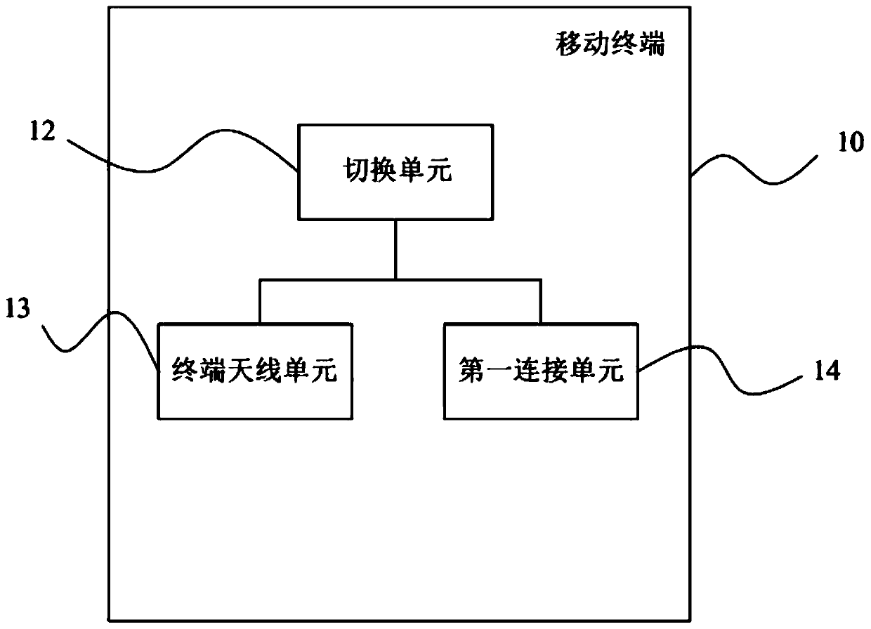
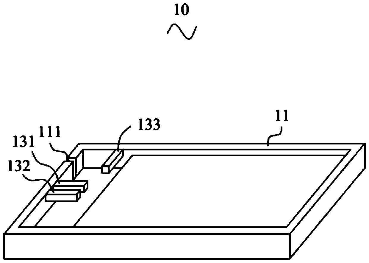
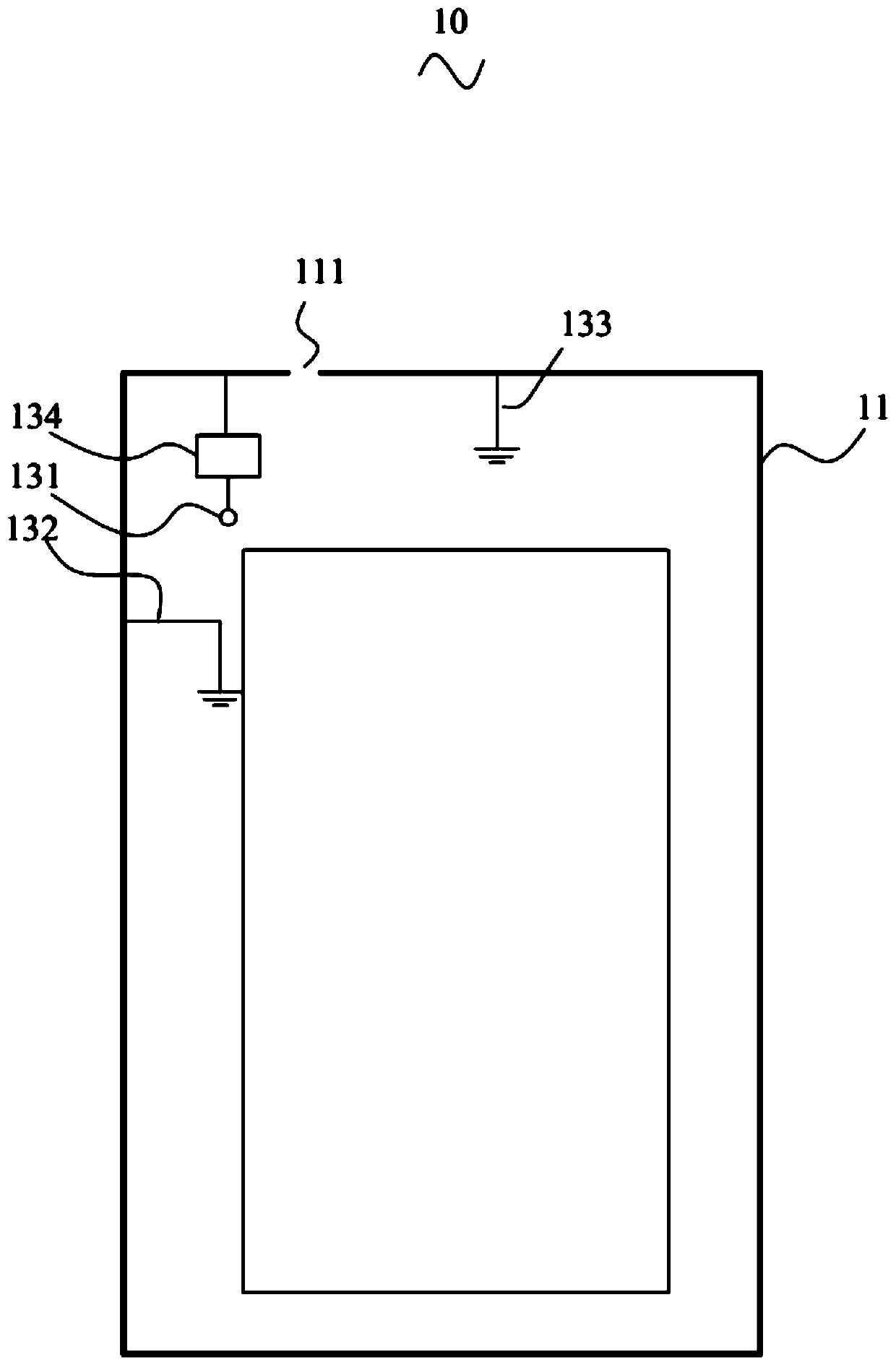
The invention provides a mobile terminal and an antenna switching method. The mobile terminal comprises a shell, a switching unit, a terminal antenna unit and a first connection unit. The shell uses ametal frame. The terminal antenna unit is use for transmitting and receiving an antenna signal. The metal frame serves as the radiator of the terminal antenna unit. The switching unit is electricallyconnected with the terminal antenna unit and the first connection unit. The first connection unit is used for connecting the second connection unit of external antenna equipment. The external antennaequipment further comprises an external antenna unit which is electrically connected with the second connection unit. The switching unit is used for controlling the switching call between the external antenna unit and the terminal antenna unit according to the received signal strength. The problems of weak received signals and antenna isolation caused by the fact that the terminal antenna is heldcan be effectively improved and the user experience can be improved.

Description

technical field [0001] The present invention relates to the technical field of antennas, in particular to a mobile terminal and an antenna switching method. Background technique [0002] With the gradual maturity and promotion of the next-generation mobile communication technology (5G), people begin to enjoy the high-speed, low-latency, and high-reliability service experience brought by 5G technology. Important characters begin to enter the user's field of vision. People's high-speed requirements in games, audio-visual and video scenes require that more antennas and more frequency bands be inserted into the limited space of mobile phones than in the 4G era, which greatly increases the difficulty of antenna design. [0003] Simply using the solution of increasing the number of mobile phone antennas to cover the current multi-frequency and multi-mode needs, in addition to the limited space of the mobile phone, which may lead to the sacrifice of the performance of each antenna...

Claims


Application Information

Patent Timeline
Patent Type & Authority Applications(China)
IPC IPC(8): H01Q1/36H01Q1/44H01Q1/48H01Q1/50H01Q1/52H01Q21/00H01Q1/24H01Q1/22H04B7/0404H04B7/06H04B7/08
CPCH01Q1/36H01Q1/44H01Q1/48H01Q1/50H01Q1/521H01Q21/00H01Q1/242H01Q1/2258H01Q1/22H04B7/0404H04B7/0608H04B7/0814
Inventor 史悦宋博徐彬彬
Owner BLACKSHARK TECH NANCHANG CO LTD
Learn More