Shearing blade for plastic lens pouring gate

A technology of shearing blade and plastic lens, applied in the field of shearing blade, can solve the problem of easy generation of stray light on the notch surface of the lens, and achieve the effect of good formation of stray light, elimination of reflection, and improvement of imaging quality.

Pending Publication Date: 2019-12-20
ZHEJIANG SUNNY OPTICAL CO LTD
View PDF0 Cites 0 Cited by
  • Summary
  • Abstract
  • Description
  • Claims
  • Application Information

AI Technical Summary

Problems solved by technology

[0004] The purpose of the present invention is to provide a shearing blade for plastic lens gates, which solves the problem that stray light is easily generated on the notch surface of the lens

Method used


Image

  • Shearing blade for plastic lens pouring gate
  • Shearing blade for plastic lens pouring gate
  • Shearing blade for plastic lens pouring gate

Examples


Embodiment Construction

[0030] In order to more clearly describe the embodiments of the present invention or the technical solutions in the prior art, the following will briefly introduce the drawings that are used in the embodiments. Apparently, the drawings in the following description are only some embodiments of the present invention, and those skilled in the art can also obtain other drawings according to these drawings without creative efforts.

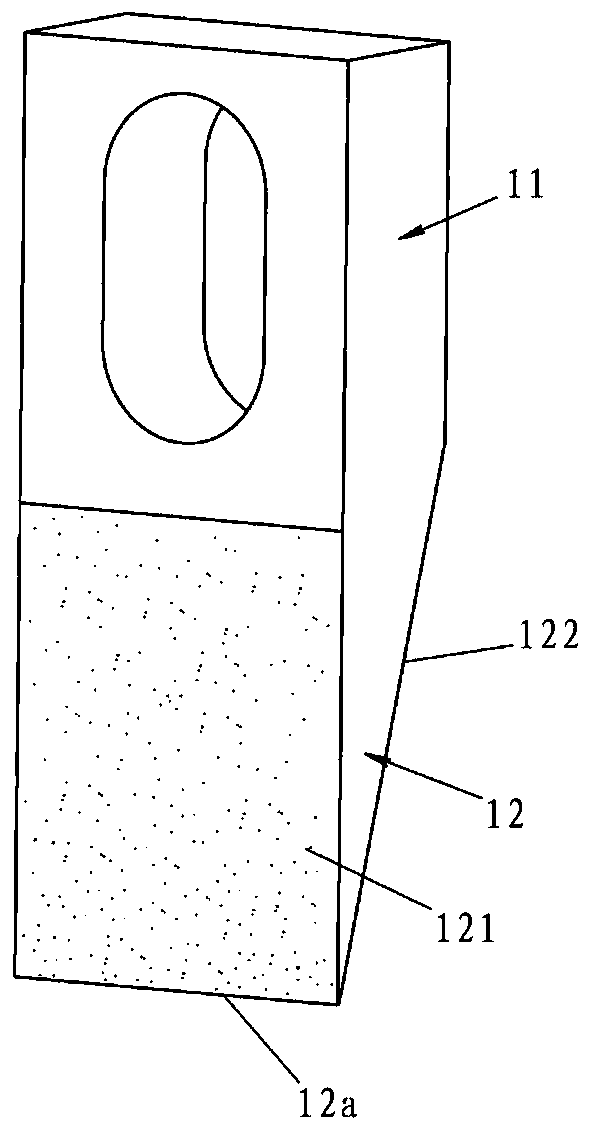
[0031] When describing the embodiments of the present invention, the terms "vertical", "transverse", "upper", "lower", "front", "rear", "left", "right", "vertical", " The orientation or positional relationship expressed by "horizontal", "top", "bottom", "inner" and "outer" is based on the orientation or positional relationship shown in the relevant drawings, which are only for the convenience of describing the present invention and simplifying the description, and It is not to indicate or imply that the device or element referred to must have a particu...


PUM

PropertyMeasurementUnit
surface roughnessaaaaaaaaaa

Abstract

The invention relates to a shearing blade for a plastic lens pouring gate. The shearing blade comprises a positioning portion and a shearing portion connected with the positioning portion; in the thickness direction of a shearing blade body, a first surface and a second surface are arranged oppositely on the shearing portion; in the direction away from the positioning portion, the thickness of theshearing portion gradually decreases, and the first surface and the second surface intersect at the farthest end to form a knife-edge structure; and the first surface is a rough surface. The first surface of the shearing portion is arranged as the rough surface, so that when a plastic lens is sheared by the shearing blade, the first surface can be used for directly processing the shearing surfaceon the plastic lens into the rough surface; and the reflection effect of a traditional smooth shearing surface on light is eliminated, so that the shearing surface formed by using the shearing bladehas a good suppression effect on the formation of stray light, and the shearing blade is beneficial to improving the imaging quality of the lens.

Description

technical field [0001] The invention relates to a shearing blade, in particular to a shearing blade used for a gate of a plastic lens. Background technique [0002] In recent years, with the increasing development of portable electronic devices such as mobile phones and tablet computers, miniaturized or even ultra-miniature lenses mounted on such devices have also begun to flourish. As a result, users not only put forward higher requirements for the imaging resolution capability of the lens, but also require the lens to have better stray light suppression capability. [0003] Since there are more and more imaging lenses in the existing miniaturized lens modules, most of the imaging lenses are made by injection molding. Considering the processing of the plastic lens in the subsequent process, before it is boxed, it is necessary to use a lens gate cutting blade to cut the glue inlet of the plastic lens. According to the current technology, the edge of the lens gate shearing ...

Claims


Application Information

Patent Timeline
Patent Type & Authority Applications(China)
IPC IPC(8): B26D1/00B29C45/38B29L11/00
CPCB26D1/0006B26D2001/0066B29C45/38B29L2011/0016
Inventor 朱国芳陈江洲秦根冯海东余青波钱峰
Owner ZHEJIANG SUNNY OPTICAL CO LTD
Why Eureka
Try Eureka