
Wind energy raindrop energy composite energy collecting device

A kind of energy harvesting and composite technology, applied in measuring devices, electromechanical devices, wind power generation, etc., can solve the problems of low energy capture efficiency, ineffective use of energy, poor stability, etc.

Pending Publication Date: 2019-12-20
SUZHOU UNIV
View PDF0 Cites 13 Cited by
  • Summary
  • Abstract
  • Description
  • Claims
  • Application Information

AI Technical Summary

Problems solved by technology

Existing raindrop energy collectors use the friction between raindrops and films to generate power, but the stability of friction power generation is also related to whether the rainfall continues. If the rain is intermittent, it will be difficult to continue
Therefore, only one form of energy conversion is used to collect raindrop energy, and the power generation efficiency is low and the stability is poor.
[0006] There are many kinds of energy in the natural environment, such as solar energy, wind energy, ocean energy, vibration energy, raindrop energy, etc., but the existing small energy harvesting devices generally can only collect a certain form of energy for power generation, such as the existing technology However, in some weather conditions, wind energy is often accompanied by raindrop energy, which will cause one of the energies to be unable to be effectively used, and the energy capture efficiency is relatively low. low power generation efficiency

Method used


Image

  • Wind energy raindrop energy composite energy collecting device
  • Wind energy raindrop energy composite energy collecting device
  • Wind energy raindrop energy composite energy collecting device

Examples


Embodiment Construction

[0032] The following will clearly and completely describe the technical solutions in the embodiments of the present invention with reference to the accompanying drawings in the embodiments of the present invention. Obviously, the described embodiments are only some, not all, embodiments of the present invention. Based on the embodiments of the present invention, all other embodiments obtained by persons of ordinary skill in the art without making creative efforts belong to the protection scope of the present invention.

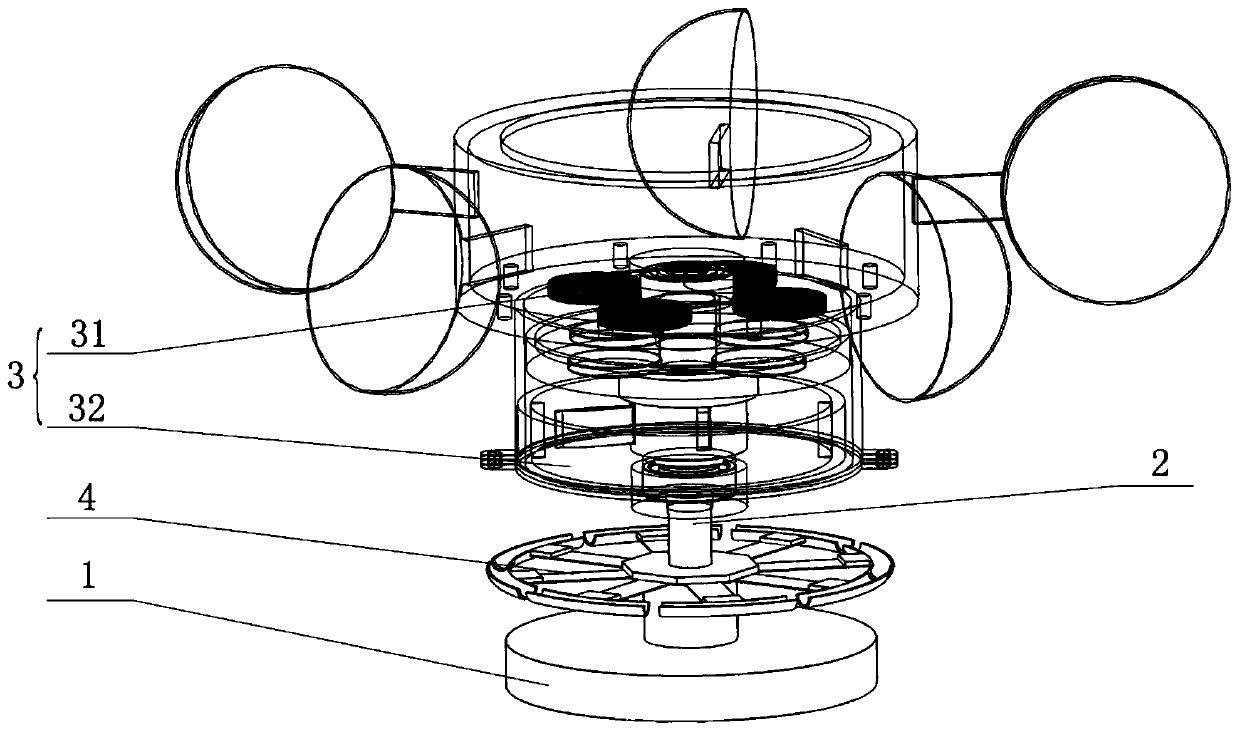
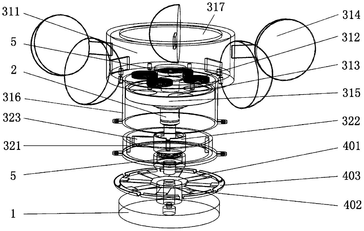
[0033] Please refer to figure 1 , figure 2 with Figure 7 , figure 1 It is a schematic diagram of the overall structure of a specific embodiment provided by the present invention, figure 2 for figure 1 The schematic diagram of the decomposition structure, Figure 7 for figure 1 The specific structural schematic diagram of the connecting shaft 2 shown in .

[0034]In a specific embodiment provided by the present invention, the wind energy raindrop ener...


PUM


Abstract

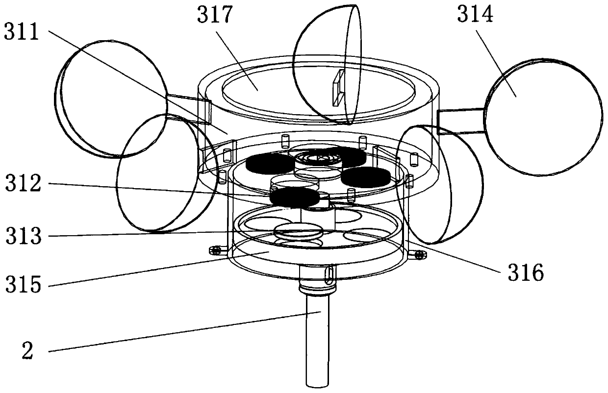
The invention discloses a wind energy raindrop energy composite energy collecting device. The wind energy raindrop energy composite energy collecting device comprises a base, a connecting shaft vertically arranged on the base, a wind power generation mechanism rotatably sleeved on the connecting shaft and used for rotating under the wind driving to generate electricity and a raindrop energy generation mechanism sleeved on the connecting shaft and used for vibrating under the driving of the raindrop impact force to generate electricity. According to the wind energy raindrop energy composite energy collection device, the wind power generation mechanism and the raindrop energy power generation mechanism are integrated through the base and the connecting shaft; when the wind energy raindrop energy composite energy collection device is used in a natural environment, wind energy and raindrop energy can be collected at the same time to generate power; compared with a single energy harvestingpower generation mechanism in the prior art, the wind energy raindrop energy composite energy collection device can realize a composite energy harvesting mechanism of wind energy and raindrop energy,improves the capture utilization rate of natural environment energy, adopts an electromagnetic, piezoelectric and friction electric composite power generation mechanism, and improves the power generation efficiency.

Description

technical field [0001] The invention relates to the technical field of power generation, in particular to a wind energy raindrop energy composite energy collection device. Background technique [0002] At present, the micro-energy technology based on environmental energy acquisition and conversion mainly includes the conversion of solar energy, thermal energy, wind energy, vibration energy and other energy into electrical energy. [0003] Among them, solar power generation technology is relatively mature, but there are still problems such as high cost, low conversion efficiency, restrictions by natural conditions such as day and night, season, geographical latitude and altitude, and difficulty in using it in cloudy, cloudy and rainy weather. Especially in some tropical rainforest areas and rainy cities, solar power generation has been greatly restricted. In addition to solar energy, wind energy and raindrop energy are abundant in nature, clean and renewable, and can adapt t...

Claims


Application Information

Patent Timeline
Patent Type & Authority Applications(China)
IPC IPC(8): F03D9/25F03D3/00F03D3/06F03D13/20H02K35/04H02N1/04H02N2/18G01W1/02
CPCF03D9/008F03D9/25F03D3/005F03D3/062F03D13/20F03D3/061H02K35/04H02N1/04H02N2/183H02N2/186G01W1/02Y02E10/728Y02E10/74
Inventor 刘会聪黄曼娟侯诚杨湛孙立宁
Owner SUZHOU UNIV
Learn More