A pipe inner wall walking device for measuring the roughness of a long pipe and its working method

A walking device and roughness technology, which is applied in the field of the inner wall walking device for measuring the roughness of long pipes, and can solve problems such as staying in the pipe and being blocked by obstacles

Active Publication Date: 2021-01-29
GUANGDONG VOCATIONAL & TECHNICAL COLLEGE
View PDF7 Cites 0 Cited by
  • Summary
  • Abstract
  • Description
  • Claims
  • Application Information

AI Technical Summary

Problems solved by technology

[0009] The main technical problem to be solved by the present invention is to provide a tube inner wall walking device for measuring the roughness of a long tube and its working method. The movement of the shaped pipe, the device can move stably in the pipe, adapting to pipes of different diameters, the device has multiple independent moving mechanisms, which can prevent the device from staying in the pipe due to equipment failure

Method used


Image

  • A pipe inner wall walking device for measuring the roughness of a long pipe and its working method
  • A pipe inner wall walking device for measuring the roughness of a long pipe and its working method
  • A pipe inner wall walking device for measuring the roughness of a long pipe and its working method

Examples


specific Embodiment approach 1

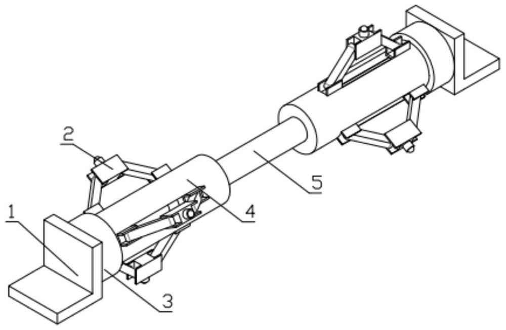
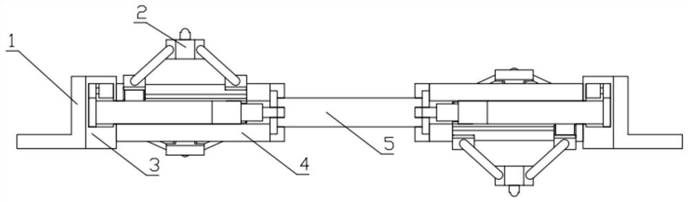
[0049] Combine below Figure 1-16 Describing this embodiment, a pipe inner wall walking device for measuring the roughness of a long pipe includes a detector mounting plate 1, a pipe wall moving mechanism 2, a power mechanism 3, an adjustment mechanism 4, and a rubber rod 5, characterized in that: the said The number of adjustment mechanisms 4 is two, and the positions are relatively symmetrical. The rubber rod 5 is located between the two adjustment mechanisms 4. The adjustment mechanism 4 is connected with the rubber rod 5 through the groove gap, and the power mechanism 3 is fixed on the other side of the adjustment mechanism 4. At one end, there are six pipe wall moving mechanisms 2, which are installed on two adjusting mechanisms 4 on average. The pipe wall moving mechanism 2 and the adjusting mechanism 4 are connected by a groove gap, and the detector mounting plate 1 is installed and fixed on the power mechanism 3. the other end of the .

specific Embodiment approach 2

[0051] Combine below Figure 1-16 This embodiment will be described. This embodiment will further describe the first embodiment. The pipe wall moving mechanism 2 includes an electric universal wheel 2-1, a universal wheel installation connector 2-2, a hinge rod 2-3, a U-shaped wheel The connecting piece 2-4, the moving foot structure 2-5, the electric universal wheel 2-1 is installed on the universal wheel installation connecting piece 2-2, and the number of hinge rods 2-3 is two, which are respectively located on the universal wheel The left and right sides of the connecting piece 2-2 are installed, and the universal wheel mounting connecting piece 2-2 is hinged with the hinge rod 2-3. There are two U-shaped connecting pieces 2-4, and the number of the hinge rod 2-3 is two. The bottom end is hinged with the U-shaped connector 2-4, and the bottom of one U-shaped connector 2-4 is fixed with a movable foot structure 2-5; the movable foot structure 2-5 includes a slider 2-5-1, a ...

specific Embodiment approach 3

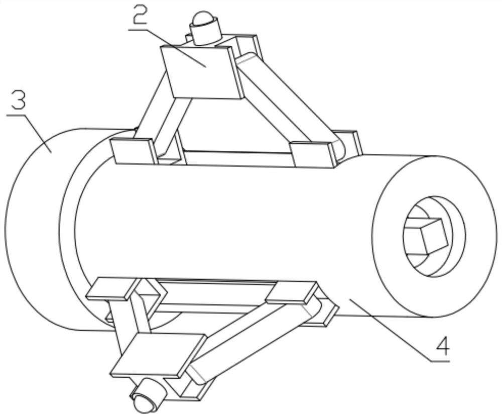
[0053] Combine below Figure 1-16 This embodiment will be described. This embodiment will further describe Embodiment 1. The power mechanism 3 includes a limit connection piece 3-1, a motor 3-2, and a motor gear 3-3. The motor 3-2 is fixed on the limit connection In the slot of the component 3-1, the motor gear 3-3 is installed on the motor 3-2, and the detector mounting plate 1 is fixed on the limit connecting component 3-1.


PUM


Abstract

The invention relates to a pipe inner wall walking device, more specifically a pipe inner wall walking device for measuring the roughness of a long pipe and its working method, including a detector mounting plate, a pipe wall moving mechanism, a power mechanism, an adjustment mechanism, a rubber Rod, this device can carry two kinds of equipment at the same time, can solve the problem of obstacles blocking, can realize the movement of curved pipes and curved pipes, the device can move stably in the pipe, adapt to pipes of different diameters, the device consists of multiple independent A shifting mechanism that prevents device failure from causing the device to remain in the tube. There are two adjustment mechanisms, and the positions are relatively symmetrical. The rubber rod is located between the two adjustment mechanisms. The adjustment mechanism and the rubber rod are connected through a groove gap. The power mechanism is fixed at the other end of the adjustment mechanism. There are six moving mechanisms, which are evenly installed on two adjusting mechanisms, and the pipe wall moving mechanism and the adjusting mechanism are connected through groove gaps.

Description

technical field [0001] The invention relates to a pipe inner wall walking device, in particular to a pipe inner wall walking device for measuring the roughness of a long pipe and a working method thereof. Background technique [0002] Pipes are used in various fields, and the roughness of the inner wall of the pipeline affects the transmission speed of the pipeline and the service life of the pipeline. When testing the roughness of the inner wall of the pipeline, it is often necessary to place the detection equipment on the moving device in the pipe. Devices often have the following disadvantages: [0003] 1. An existing device can only carry a single device or a limited area to carry the device. [0004] 2. The existing equipment cannot turn or the turning mechanism cannot meet the actual use situation. [0005] 3. Existing equipment cannot achieve over obstacles. [0006] 4. Once the existing equipment fails, it cannot work, causing all equipment to stay in the tube. ...

Claims


Application Information

Patent Timeline
Patent Type & Authority Patents(China)
IPC IPC(8): F16L55/32F16L55/40G01B21/30F16L101/30
CPCF16L55/32F16L55/40F16L2101/30G01B21/30
Inventor 王北一
Owner GUANGDONG VOCATIONAL & TECHNICAL COLLEGE
Why Eureka
Try Eureka