
Refrigerant mixing and injecting machine and refrigerant mixing and injecting method

A refrigerant and mixed injection technology, applied in refrigerators, refrigeration components, refrigeration and liquefaction, etc., can solve the problems of low production efficiency, high labor intensity, complicated steps, etc., and achieve easy charging, easy equipment maintenance, and reasonable design. Effect

Pending Publication Date: 2019-12-20
佛山市顺德区鼎联智能科技有限公司
View PDF0 Cites 0 Cited by
  • Summary
  • Abstract
  • Description
  • Claims
  • Application Information

AI Technical Summary

Problems solved by technology

[0003] However, because the pressures of different types of refrigerants are different, the current production plant is based on the different pressures of the refrigerants, first quantitatively injecting the lowest-pressure refrigerant into the refrigeration system, and then quantitatively injecting high-pressure refrigerants from low to high pressure. Due to the complicated steps of this production process, the production efficiency is low and the labor intensity is high, and the refrigerants that need to be mixed in proportion are injected into the refrigeration system successively. Due to the different pressure and specific gravity of the refrigerants, different types of refrigerants enter After the refrigeration system cannot be fully mixed, it needs to run for a period of time before the refrigeration system can reach the technical index of mixing in proportion, which will affect the initial operation of the refrigeration equipment. Obviously, this production process does not meet the requirements for the production of this refrigeration equipment. skills requirement

Method used


Image

  • Refrigerant mixing and injecting machine and refrigerant mixing and injecting method

Examples


Embodiment 1

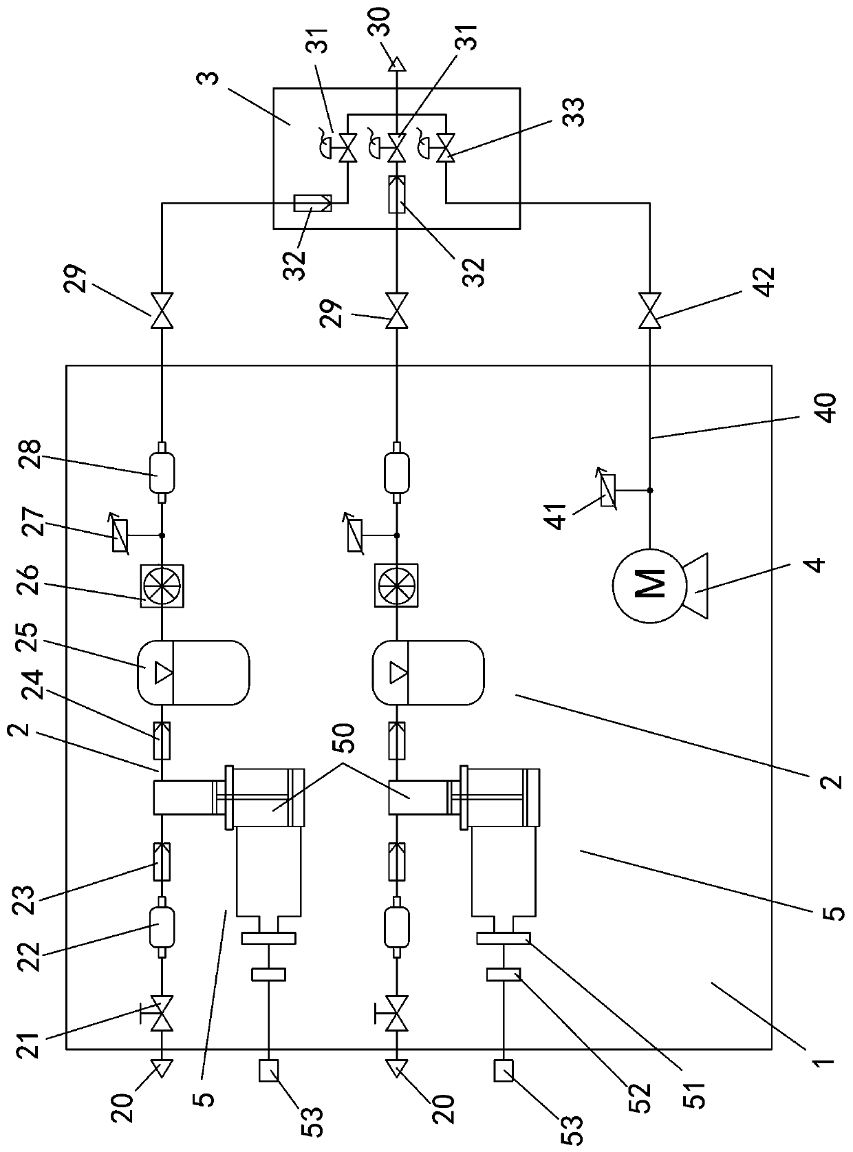
[0023] Embodiment one, see figure 1 As shown, a refrigerant mixing injection machine includes a host 1, two delivery pipes 2, a vacuum pump 4 and a flow charging valve assembly 3, the delivery pipeline 2 and the vacuum pump 4 are arranged in the host 1, and each delivery pipeline 2 ends They are the input interface 20 and the output interface 29 respectively. The input interface 20 and the output interface 29 of each delivery pipeline 2 are set on the host machine 1 , and the output interfaces 29 of the two delivery pipelines 2 are connected to the flow filling valve assembly 3 .

[0024] Wherein, each of the delivery pipelines 2 is sequentially provided with an input valve 21, an input filter 22, an input check valve 23, a pressure regulating device 5, a second check valve 24, an accumulator 25, a flow meter 26, a pressure A sensor 27 and an output filter 28 are arranged successively between the input interface 20 and the output interface 29 . The pressure regulating device ...


PUM


Abstract

The invention discloses a refrigerant mixing and injecting machine. The refrigerant mixing and injecting machine comprises at least two conveying pipelines, a vacuum pump and a flowing injection valveassembly; the two end of each conveying pipeline is provided with an input interface and an output interface respectively; the output interface of each pipeline is connected to the flowing injectionvalve assembly; a pressure regulating device, an energy accumulator and a flowmeter are arranged on each pipeline; the flowing injection valve assembly comprises an injection joint, a vacuum valve andinjection valves, wherein the injection valves are corresponding to the conveying pipelines in number; each injection valve is connected to the output interface of one conveying pipeline; the vacuumvalve is connected to the vacuum pump; and all the injection valves and the vacuum valve are connected in parallel and are connected to the injection joint in series. The refrigerant mixing and injecting machine has the advantages that the design is reasonable, different refrigerants are regulated to the same pressure in the different pipelines through the pressure regulating devices so as to be injected into refrigeration equipment simultaneously through the flowing injection valve assembly, so that the different refrigerants can be conveniently and uniformly mixed, and the initial operatingperformance of the refrigeration equipment is improved.

Description

technical field [0001] The invention relates to the technical field of refrigeration equipment, in particular to a refrigerant mixing injection machine. Background technique [0002] With the continuous research and development and technological innovation of refrigeration equipment, a single refrigerant is not suitable for the operating conditions of refrigeration equipment. Two or more different types of refrigerants must be operated in the same refrigeration system to achieve the purpose of improving efficiency. . However, two or more refrigerants operating in the same refrigeration system must be mixed according to their respective injection weights to achieve the best performance. Therefore, when producing this type of refrigeration equipment, it is necessary to vacuumize the refrigeration equipment and Inject refrigerants of different types and weights according to technical requirements, so as to achieve the purpose of operating two or more refrigerants in the same r...

Claims


Application Information

Patent Timeline
IPC IPC(8): F25B45/00
CPCF25B45/00
Inventor 冯思远冯思聪
Owner 佛山市顺德区鼎联智能科技有限公司
Learn More