Auxiliary positioning device for apron board bracket of EMU and positioning method thereof

A technology for assisting positioning and EMUs, which is applied to active optical measurement devices, measurement devices, and optical devices, etc., can solve problems such as many human errors, poor positioning accuracy, and cumbersome solution process of trigonometric function measurement and calculation process.

Active Publication Date: 2019-12-20
CRRC CHANGCHUN RAILWAY VEHICLES CO LTD
View PDF6 Cites 2 Cited by
  • Summary
  • Abstract
  • Description
  • Claims
  • Application Information

AI Technical Summary

Problems solved by technology

[0014] In order to solve the existing EMU skirt plate support positioning method, the surveying and mapping method includes a large number of traditional manual surveying and mapping processes of measuring markings and arranging plumb lines, which introduces more human errors, is not rigorous and scientific enough, and contains The trigonometric function measurement and calculation process is cumbersome, and many human errors are introduced, which leads to the difficulty in implementing the surveying and mapping process of the old apron bracket positioning method, high labor intensity, poor positioning accuracy, and low operating efficiency. The present invention provides a Auxiliary positioning device and positioning method for EMU skirt plate support

Method used


Image

  • Auxiliary positioning device for apron board bracket of EMU and positioning method thereof
  • Auxiliary positioning device for apron board bracket of EMU and positioning method thereof
  • Auxiliary positioning device for apron board bracket of EMU and positioning method thereof

Examples


Embodiment Construction

[0066] The present invention will be further described in detail below in conjunction with the accompanying drawings.

[0067] like Figure 5 to Figure 9 As shown, the auxiliary positioning device for the apron bracket of the EMU of the present invention includes: a horizontal reference base 5, a bubble level 6, two horizontal slider devices 7, a T-shaped chute centerline positioning mechanism 8, a linear laser 9 and a laser rangefinder 10. The right side of the upper end face of the horizontal reference base 5 is provided with a base horizontal chute 5-1 along the Y-axis direction, and the left side of the upper end face of the horizontal reference base 5 is provided with a base vertical passage along the vertical Z-axis direction. Hole 5-2; the two horizontal slider devices 7 are both slidably connected to the base horizontal chute 5-1; The block device 7 is slidably connected to the right side of the upper end surface of the horizontal reference base 5;

[0068]The T-shap...


PUM


Abstract

An auxiliary positioning device for an apron board bracket of EMU and a positioning method thereof belong to the technical field of rail vehicle apron board bracket positioning. The device comprises ahorizontal reference base, a bubble level, two horizontal slider devices, a T-shaped chute centerline positioning mechanism, a linear laser and a laser rangefinder, wherein the right side of the upper end surface of the horizontal reference base is provided with a base horizontal chute along the Y-axis direction, and the left side of the upper end surface of the horizontal reference base is provided with a base vertical through hole along the direction vertical to the Z axis; the two horizontal slider devices are slidingly connected to the base horizontal chute; both the linear laser and thelaser rangefinder are in sliding connection with the right side of the upper end surface of the horizontal reference base through a corresponding horizontal slider device in a vertical upward positionon the optical axis; and the middle section of the T-shaped chute centerline positioning mechanism is coaxially fixed with the base vertical through hole. The auxiliary positioning device for the apron board bracket of EMU and the positioning method thereof provided by the invention optimize the surveying and mapping process, enable the auxiliary positioning device of the apron board bracket to obtain the advantages such as accurate positioning, easy operation and visible results, and can greatly improve measurement accuracy and positioning efficiency.

Description

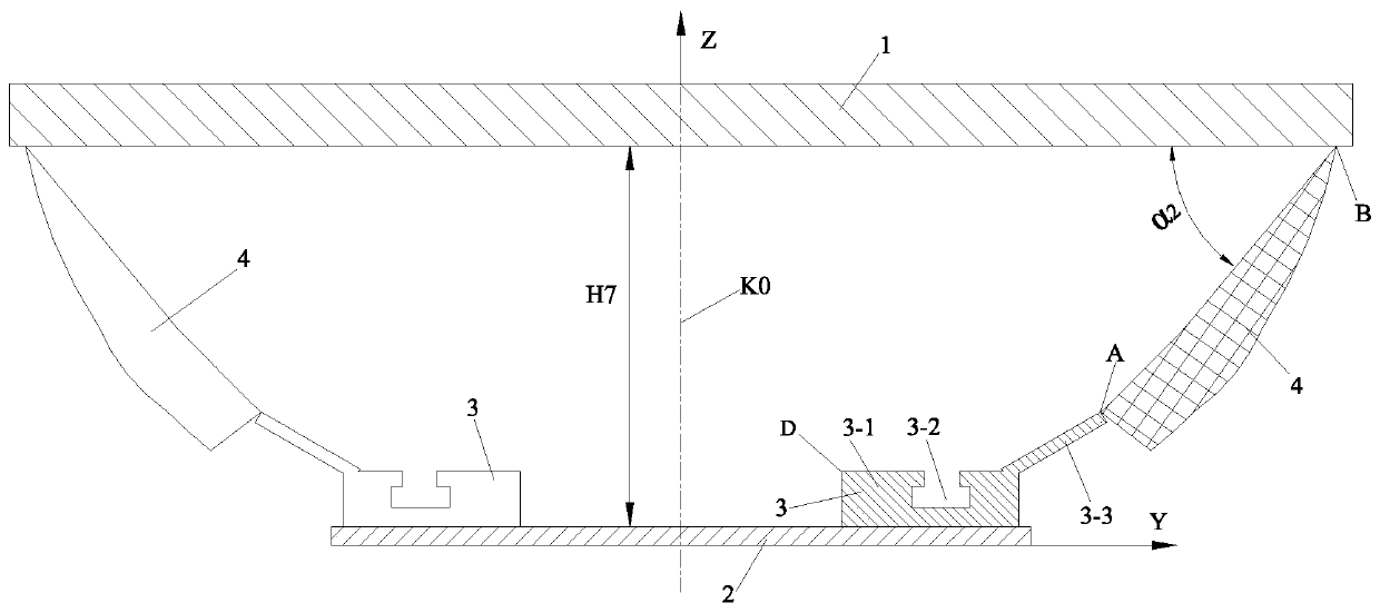
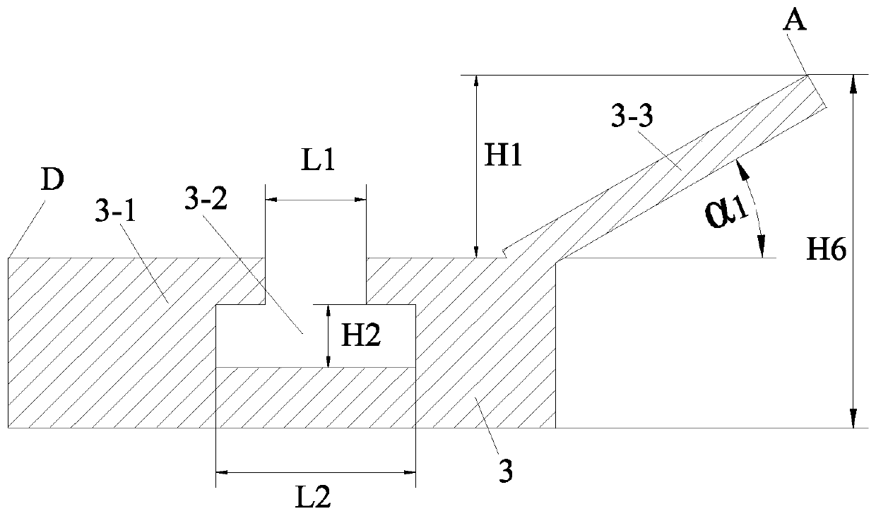
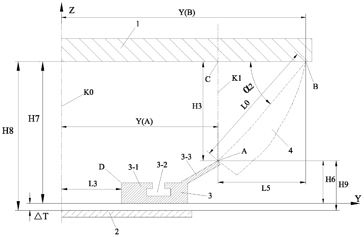
technical field [0001] The invention belongs to the technical field of rail passenger car skirt plate bracket positioning, and in particular relates to an auxiliary positioning device for an EMU skirt plate bracket and a positioning method thereof. Background technique [0002] like figure 1 and figure 2 As shown, the vertical Z-axis is taken as the symmetrical center line K0, and the cross-section of the underframe of the rail passenger car such as the EMU is mirror-symmetrically divided into two parts: left and right. According to the size of the standard drawing, the lower end surface of the steel structure 1 The theoretical distance of the upper end face of the plate 2 is H7. The apron bracket 3 includes a sliding rail body 3-1 with a rectangular cross-sectional outer profile and a apron hinge shaft seat 3-3 with an angle of α1 with the upper end horizontal plane of the sliding rail body 3-1; the rectangular sliding rail body 3-1 The middle of the upper end face is p...

Claims


Application Information

Patent Timeline
Patent Type & Authority Applications(China)
IPC IPC(8): G01C15/00G01C9/24G01C3/00G01B11/06
CPCG01C15/002G01C9/24G01C3/00G01B11/0608Y02T30/00
Inventor 李光磊邵越刘芳铭
Owner CRRC CHANGCHUN RAILWAY VEHICLES CO LTD
Why Eureka
Try Eureka