
Backlight module and display device

A backlight module, light source technology, applied in the direction of light guide, optics, optical components, etc., can solve the problems of transparency, light output rate and low contrast

Active Publication Date: 2019-12-20
BOE TECH GRP CO LTD
View PDF13 Cites 0 Cited by
  • Summary
  • Abstract
  • Description
  • Claims
  • Application Information

AI Technical Summary

Problems solved by technology

[0003] However, the transparency, light extraction rate and contrast of the current backlight module structure design are low

Method used


Image

  • Backlight module and display device
  • Backlight module and display device
  • Backlight module and display device

Examples


Embodiment Construction

[0055] The following describes the embodiments of the present invention in detail, and those skilled in the art will understand that the following embodiments are intended to explain the present invention, and should not be regarded as limiting the present invention. Unless otherwise specified, in the following examples that do not explicitly describe specific techniques or conditions, those skilled in the art can carry out according to commonly used techniques or conditions in this field or according to product instructions.

[0056] In one aspect of the present invention, the present invention provides a backlight module.

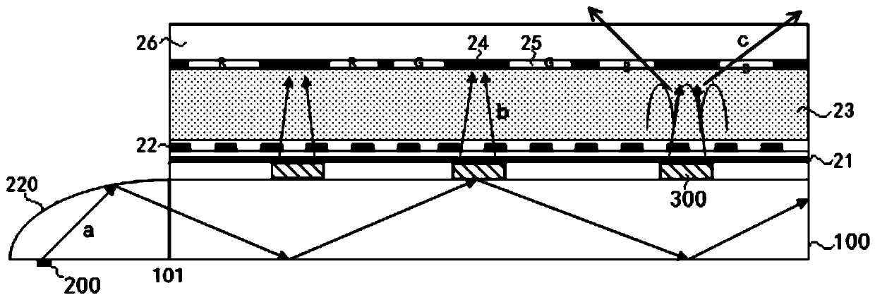
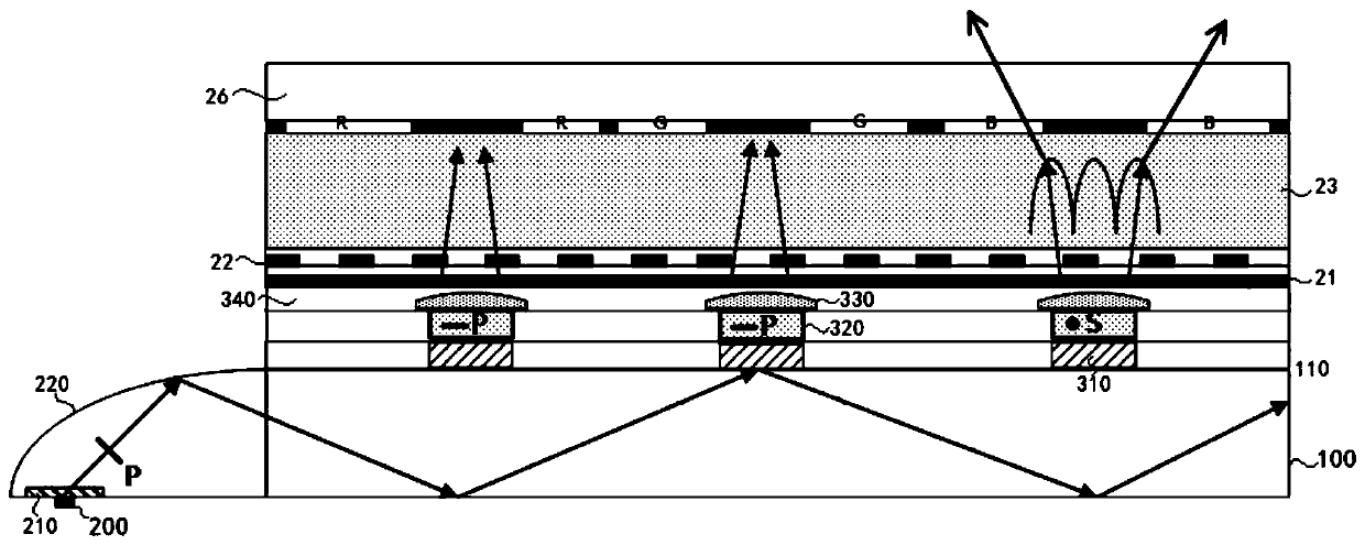
[0057] According to an embodiment of the present invention, refer to figure 1 , the backlight module includes a light guide plate 100, a light source 200, and a plurality of light-taking structures 300; wherein, the light guide plate 100 has a light-emitting surface 110 and a light-incoming surface 101; the light source 200 is arranged on the light-incomi...


PUM


Abstract

The invention provides a backlight module and a display device. The backlight module comprises a light guide plate, a light source and a plurality of light extraction structures, wherein the light guide plate has a light emergent surface and a light incident surface; the light source is arranged on the light incident surface; and the plurality of light extraction structures are arranged on the light emergent surface, and a light beam emitted from the light source is totally reflected in the light guide plate and is converged, and is emitted by means of the light extraction structures in a darkstate display state, or is diverged and emitted from the light extraction structures in a gray scale display state. According to the backlight module provided by the invention, the light extraction structures on the light emergent surface of the light guide plate can enable the light beam emitted from the light source to be totally reflected in the light guide plate and then to be converged and emitted or diverged and emitted, so that the display device comprising the backlight module has higher transparency, higher contrast ratio and higher light emitting rate.

Description

technical field [0001] The present invention relates to the field of display technology, in particular, the present invention relates to a backlight module and a display device. Background technique [0002] The display device at the present stage can modulate the Lambertian light emitted by the light-emitting diode (LED) light source through the free-form surface reflector, and couple it into the light guide plate at a certain angle. The take-out grating exits above or below the setting. Among them, the function of taking out the grating is to take out the large-angle light that is totally reflected and propagated in the light guide plate at a collimated angle, so as to realize a collimated light source with higher transmittance. [0003] However, the structural design of the current backlight module has low transparency, light extraction rate and contrast. Contents of the invention [0004] The present invention is accomplished based on the following findings: [0005...

Claims


Application Information

Patent Timeline
IPC IPC(8): G02B6/00G02F1/13357
CPCG02B6/005G02B6/0056G02F1/133615G02F1/133512G02B6/002G02B6/0031G02B6/0016G02B6/0063G02F1/133602G02F1/13362G02F1/13363
Inventor 洪涛
Owner BOE TECH GRP CO LTD
Learn More