Optical imaging element, and manufacturing method of optical imaging element

An optical imaging and component manufacturing technology, applied in optical components, optics, instruments, etc., can solve problems such as the commercial promotion and large-scale application of medium-free aerial imaging technology, insufficient resolution and clarity of aerial imaging, and affecting user experience. , to achieve the effect of expanding applicability, ingenious and simple manufacturing method, and improving resolution

Pending Publication Date: 2019-12-20
XIANGHANG SHANGHAI TECH CO LTD
View PDF7 Cites 18 Cited by
  • Summary
  • Abstract
  • Description
  • Claims
  • Application Information

AI Technical Summary

Problems solved by technology

[0002] In the prior art, the medium-free aerial imaging technology mainly adopts the micro-channel matrix optical waveguide plate, which is realized by re-converging in the air through two reflections of two layers of transparent materials arranged orthogonally through the optical path, and can reflect point light sources, line Light source and surface light source are still point light source, line light source and surface light source after converging in the air. This special light path reflection effect makes the aerial imaging technology move toward practical application. However, the two layers of transparent materials arranged orthogonally are now used The realized micro-channel matrix optical waveguide flat plate has insufficient resolution and clarity of aerial imaging, which not only affects user experience, but also puts forward higher requirements for application scenarios, resulting in the commercial promotion and large-scale application of medium-free aerial imaging technology being restricted. Great constraints

Method used


Image

  • Optical imaging element, and manufacturing method of optical imaging element
  • Optical imaging element, and manufacturing method of optical imaging element
  • Optical imaging element, and manufacturing method of optical imaging element

Examples


Embodiment Construction

[0062] The preferred embodiments of the present invention will be described in detail below in conjunction with the accompanying drawings, and the present invention will be further elaborated.

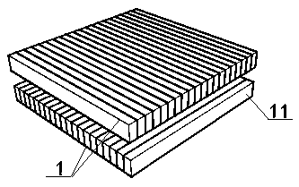
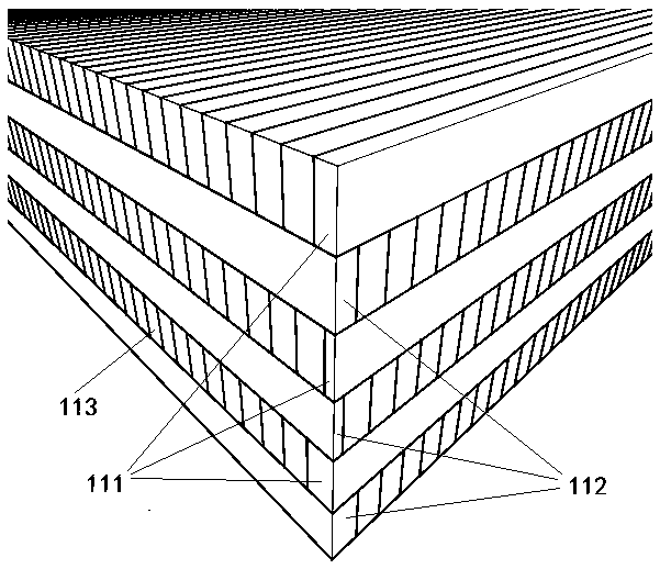
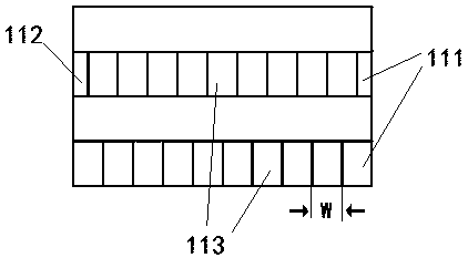
[0063] First, combine the Figure 1~4 The optical imaging element according to the embodiment of the present invention is used for medium-free imaging in the air, and can be used for conferences, teaching, exhibitions, media, urban infrastructure, etc., and has a wide range of application scenarios.

[0064] Such as Figure 1~4 As shown, the optical imaging element of the embodiment of the present invention has a light-transmitting laminated body 1 with an even-numbered layer stacked arrangement. Wherein, each layer of light-transmitting laminated body 1 is provided with several transparent strips 11 that are attached to each other, and the surfaces that are attached to each other on the transparent strips 11 and / or the opposite surface of the surfaces that are attached to each other ...


PUM


Abstract

The invention discloses an optical imaging element and a manufacturing method thereof. The optical imaging element of the invention comprises: light-transmitting laminated bodies with the even numberof layers, wherein each layer comprises a plurality of transparent strips, reflecting surfaces are arranged on the transparent strips, and the transparent strips of the two adjacent layers of the light-transmitting laminated body are mutually orthogonal; each layer of transparent strip comprises: a first transparent strip, a second transparent strip and a plurality of third transparent strips, wherein the first transparent strip and the second transparent strip are respectively arranged at the edges of two sides of each transparent laminating body, the plurality of third transparent strips arearranged between the first transparent strip and the second transparent strip, and the sum of the widths of the first transparent strip and the second transparent strip is equal to the width of the third transparent strip. Through the staggered arrangement in the optical imaging element, the resolution of aerial imaging is greatly improved, the dependence on application scenes and use environments is reduced, the applicability is greatly expanded, and meanwhile, the manufacturing method is ingenious and simple, and a solid technical foundation is laid for batch production and large-scale commercial use.

Description

technical field [0001] The invention relates to a medium-free aerial imaging technology, in particular to an optical imaging element and a manufacturing method of the optical imaging element. Background technique [0002] In the prior art, the medium-free aerial imaging technology mainly adopts the micro-channel matrix optical waveguide plate, which is realized by re-converging in the air through two reflections of two layers of transparent materials arranged orthogonally through the optical path, and can reflect point light sources, line Light source and surface light source are still point light source, line light source and surface light source after converging in the air. This special light path reflection effect makes the aerial imaging technology move toward practical application. However, the two layers of transparent materials arranged orthogonally are now used The realized micro-channel matrix optical waveguide flat plate has insufficient resolution and clarity of a...

Claims


Application Information

Patent Timeline
Patent Type & Authority Applications(China)
IPC IPC(8): G02B27/22
CPCG02B30/35G02B30/56
Inventor 颜展洪增辉张兵韩成
Owner XIANGHANG SHANGHAI TECH CO LTD
Why Eureka
Try Eureka