Touch recognition method
An identification method and a touch technology, which are applied in the direction of instruments, electrical digital data processing, and data processing input/output process, etc., can solve the problems of high equipment manufacturing cost, inconvenient user operation, and inconvenient use
- Summary
- Abstract
- Description
- Claims
- Application Information
AI Technical Summary
Problems solved by technology
Method used
Image

Examples
Embodiment 1
[0082] The present invention provides a first preferred implementation of a touch recognition method, which includes the following steps:
[0083] The touch panel includes a touch area; the touch signal in the touch area is detected, so that the touch area is divided into several control areas; wherein, the touch panel is connected to the controller signal; the touch The control area or the control area is used to obtain and transmit control signals to the controller.
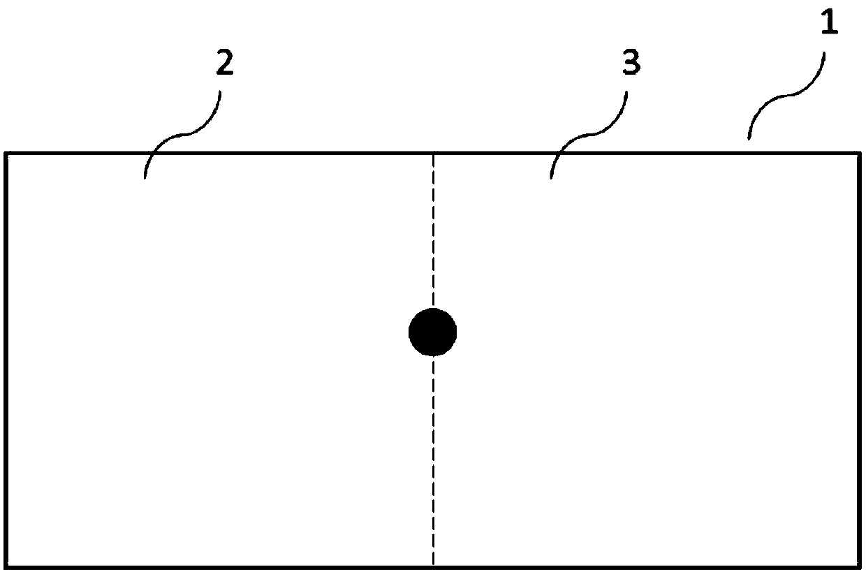
[0084] like figure 1 Shown, the course of work of this embodiment is:
[0085] After the touch area 1 receives the touch signal generated by the user's touch operation at the touch point (the solid point in the figure), the touch area will be divided into two control areas, as shown in the figure The first control area 2 and the second control area 3 . The user can operate the touch panel according to the control signals represented by different control areas.
[0086] This embodiment is the basic implement...
Embodiment 2
[0091] A preferred implementation mode of this embodiment combined with the above-mentioned embodiment, the difference between this embodiment 2 and the above-mentioned embodiment 1 is that, in this embodiment, the specific steps of dividing the touch area into several control areas include :
[0092] (1) The first implementation method:
[0093] Detecting a first touch signal in the touch area, and making the touch area in a pre-partition state according to the first touch signal;
[0094] When the first touch signal continues to exist, if a second touch signal is detected from the control area, according to the type of the second touch signal, such that:
[0095] The touch area is converted from a pre-partitioned state to a partitioned state; or,
[0096] The touch area is converted into a non-partitioned state.
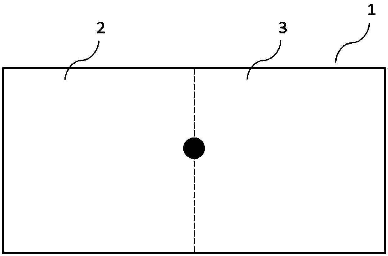
[0097] The implementation process of the above steps is illustrated below in conjunction with Figure 2:
[0098] First, as shown in Figure 2(a), detect the fir...
Embodiment 3
[0114] This embodiment is another preferred implementation mode based on the above-mentioned embodiment 2. The difference between this embodiment 3 and the above-mentioned embodiment 2 is: in this embodiment, the first touch signal is two points A touch signal, when the touch area is divided, the control area includes a first control area, a second control area and a third control area.
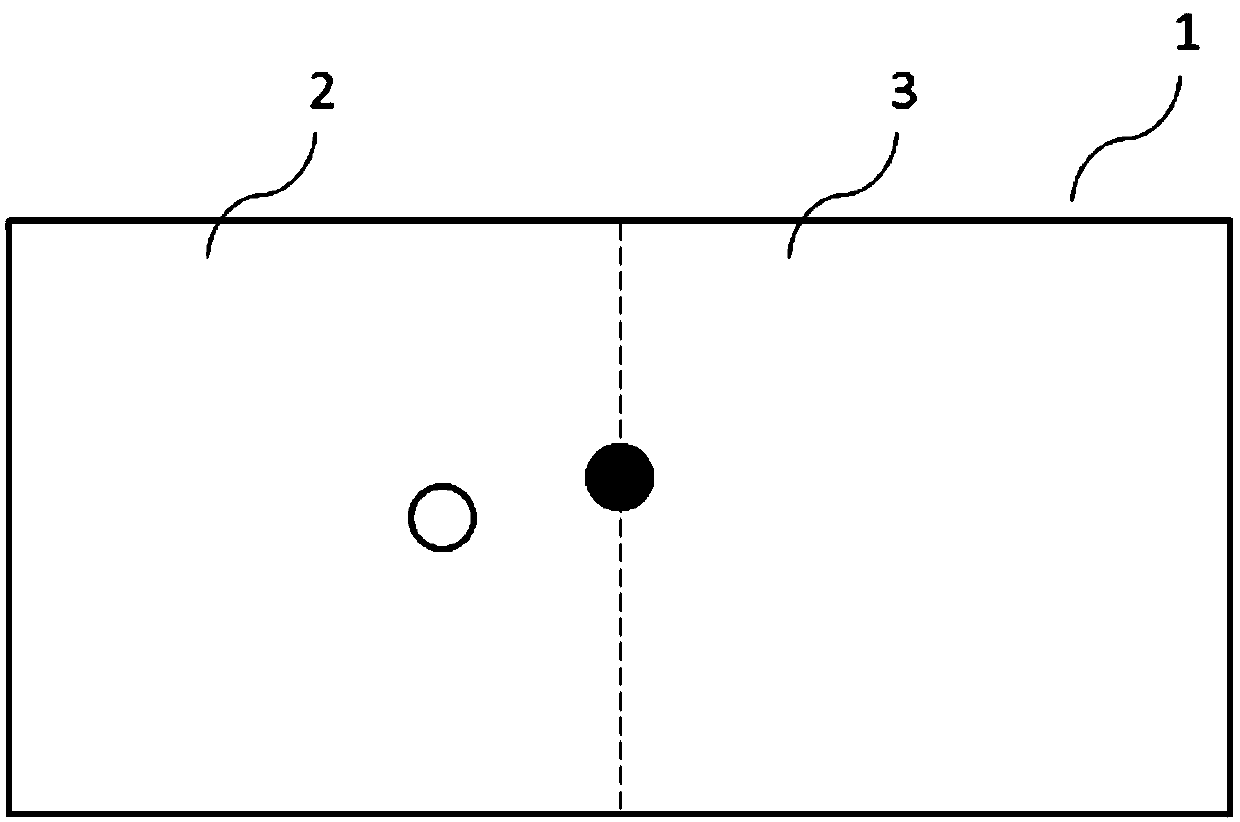
[0115] The implementation process of the above steps is illustrated below in conjunction with Figure 4:
[0116] Taking the first implementation of the above-mentioned embodiment 2 as an example, firstly, as shown in FIG. The touch signal is a contact signal, so that the touch area is in a pre-partitioned state, and then the second touch signal (hollow point) is detected. When the second touch signal is a click signal, as shown in Figure 4(b) display, transform the touch area into a partition state. The control areas obtained by partitioning are: the first control area 2 , the second contro...
PUM
 Abstract
Description
Claims
Application Information
 - R&D
- Intellectual Property
- Life Sciences
- Materials
- Tech Scout
- Unparalleled Data Quality
- Higher Quality Content
- 60% Fewer Hallucinations
Browse by: Latest US Patents, China's latest patents, Technical Efficacy Thesaurus, Application Domain, Technology Topic, Popular Technical Reports.
© 2025 PatSnap. All rights reserved.Legal|Privacy policy|Modern Slavery Act Transparency Statement|Sitemap|About US| Contact US: help@patsnap.com