
Low Magnetic Loss Alloy Magnetic Ring

A magnetic loss, magnetic ring technology, applied in the direction of inductors with magnetic cores, transformer/inductor magnetic cores, preventing/reducing unwanted electrical/magnetic influences, etc. Serious magnetic loss and other problems, to achieve the effect of reducing magnetic loss and avoiding damage

Active Publication Date: 2021-06-01
苏美尔磁性电子(惠州)有限公司
View PDF5 Cites 0 Cited by
  • Summary
  • Abstract
  • Description
  • Claims
  • Application Information

AI Technical Summary

Problems solved by technology

However, the existing magnetic rings usually use two magnetic rings with different turns to suppress high-frequency noise and low-frequency interference, which is not only troublesome, but also wastes manufacturing materials. The magnetic loss of the magnetic ring is serious during use, which affects the effect of suppressing interference.

Method used


Image

  • Low Magnetic Loss Alloy Magnetic Ring
  • Low Magnetic Loss Alloy Magnetic Ring
  • Low Magnetic Loss Alloy Magnetic Ring

Examples


Embodiment Construction

[0019] In order to make the technical means, creative features, goals and effects achieved by the present invention easy to understand, the present invention will be further described below in conjunction with specific embodiments.

[0020] In the description of the present invention, it should be noted that the terms "upper", "lower", "inner", "outer", "front end", "rear end", "both ends", "one end", "another end" The orientation or positional relationship indicated by etc. is based on the orientation or positional relationship shown in the drawings, and is only for the convenience of describing the present invention and simplifying the description, rather than indicating or implying that the referred device or element must have a specific orientation, use a specific Azimuth configuration and operation, therefore, should not be construed as limiting the invention. In addition, the terms "first" and "second" are used for descriptive purposes only, and should not be understood ...


PUM


Abstract

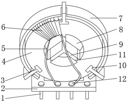
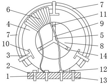
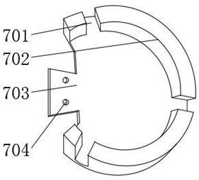
The invention discloses a low magnetic loss alloy magnetic ring, which includes a wound magnetic ring, a central hole is formed in the middle of the wound magnetic ring, and several turns of winding wires are wound on the surface of the wound magnetic ring. The outer surface is provided with a first fixed card slot, and a first fixed baffle matching with the first fixed card slot is installed inside the first fixed card slot, and the inner surface of the winding magnetic ring has a reserved block, so The reserved block is provided with a second fixed slot, and the inside of the second fixed slot is located in the center hole, and a second fixed baffle matched with the second fixed slot is installed, and the surface of the winding magnetic ring A shielding cover is installed. A low magnetic loss alloy magnetic ring described in the utility model partitions the winding magnetic ring through a fixed baffle, so that the magnetic ring can select different parts of the winding according to suppressing high-frequency noise or suppressing low-frequency interference, and the shielding cover can protect the internal A magnetic ring is wound for protection and can reduce magnetic loss.

Description

technical field [0001] The invention relates to the field of alloy magnetic rings, in particular to alloy magnetic rings with low magnetic loss. Background technique [0002] The magnetic ring is an anti-interference component commonly used in electronic circuits. It has a good suppression effect on high-frequency noise. It is generally made of ferrite materials. The magnetic ring has different impedance characteristics at different frequencies. Generally, the impedance at low frequencies Very small, when the signal frequency increases, the impedance of the magnetic ring increases sharply, the higher the signal frequency, the easier it is to radiate out, and the general signal lines have no shielding layer, then these signal lines become good antennas , to receive various messy high-frequency signals in the surrounding environment, and these signals are superimposed on the original transmitted signal, and even change the original transmitted useful signal, then under the act...

Claims


Application Information

Patent Timeline
Patent Type & Authority Patents(China)
IPC IPC(8): H01F17/06H01F27/24H01F27/34H01F27/29H01F27/32
CPCH01F17/062H01F27/24H01F27/2885H01F27/29H01F27/324H01F27/346H01F2017/065
Inventor 林致婷
Owner 苏美尔磁性电子(惠州)有限公司
Learn More