Coil component

A technology of coil components and coils, which is applied in the direction of transformer/inductor parts, electrical components, transformer/inductor coils/windings/connections, etc. It can solve problems such as cracking and composite magnetic body gaps, and achieve high-density installation, The effect of reducing the installation area

Active Publication Date: 2019-12-20
TDK CORPARATION
View PDF13 Cites 0 Cited by
  • Summary
  • Abstract
  • Description
  • Claims
  • Application Information

AI Technical Summary

Problems solved by technology

[0006] In conventional coil components, problems such as cracks or cracks sometimes occur in the composite magnetic body due to external shocks, etc.

Method used


Image

  • Coil component
  • Coil component
  • Coil component

Examples


no. 2 approach

[0133] Figure 7 It is a schematic perspective view from the side of the 2nd surface 22 of the coil component 110 which concerns on 2nd Embodiment of this invention. The coil component 110 according to the second embodiment is the same as the coil component 10 according to the first embodiment except that the shapes of the first and second metal electrodes 140 and 150 are different. Therefore, regarding the coil component 110 according to the second embodiment, only the differences from the coil component 10 will be described, and the description of the same points as the coil component 10 will be omitted.

[0134] Figure 8 yes Figure 7 The perspective view of the first and second metal electrodes 140 and 150 included in the coil component 110 is shown. Such as Figure 8 As shown, the first and second metal electrodes 140, 150 are different from the first and second metal electrodes 40, 50 shown in FIG. Everything else is the same.

[0135] Figure 9 It is a schematic p...

no. 3 approach

[0138] Figure 10 It is a schematic perspective view from the side of the 2nd surface 22 of the coil component 210 which concerns on 3rd Embodiment of this invention. The coil component 210 according to the third embodiment is the same as the coil component 110 according to the second embodiment except that the shapes of the first and second metal electrodes 240 and 250 are different. Therefore, regarding the coil component 210 according to the third embodiment, only the differences from the coil component 110 will be described, and the description of the same points as the coil component 110 will be omitted.

[0139] Composite magnetic body portion 120 of coil component 210 and Figure 7 The composite magnetic body portion 120 included in the illustrated coil component 110 is the same. However, if Figure 10 And the perspective view of the first and second metal electrodes 240, 250 is Figure 11 As shown, the first and second metal electrodes 240 , 250 are different from ...


PUM


Abstract

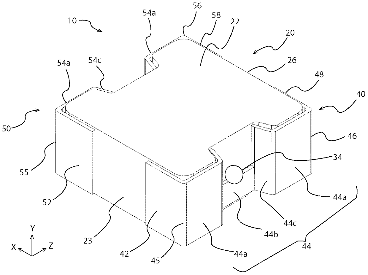
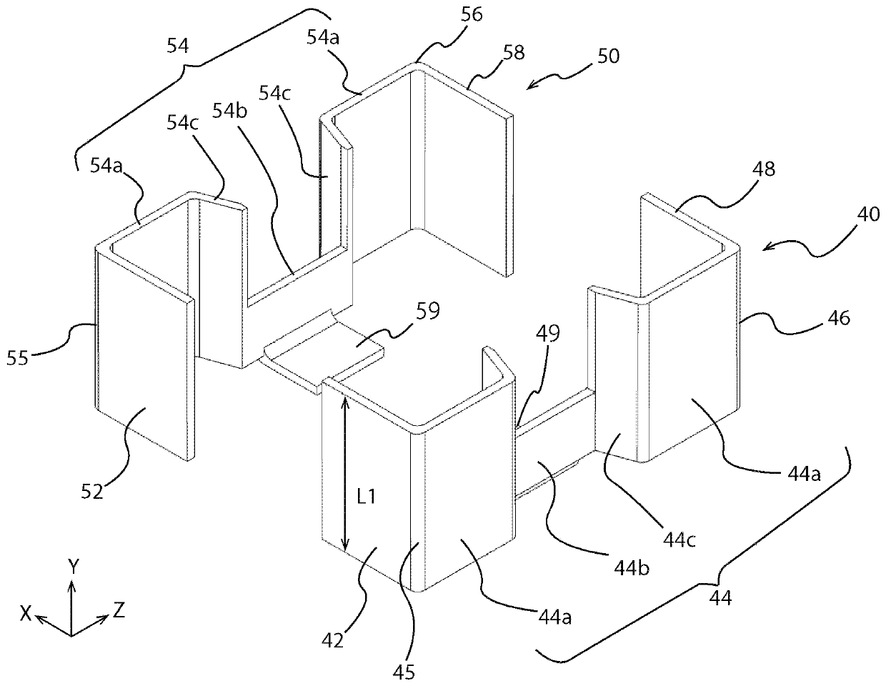
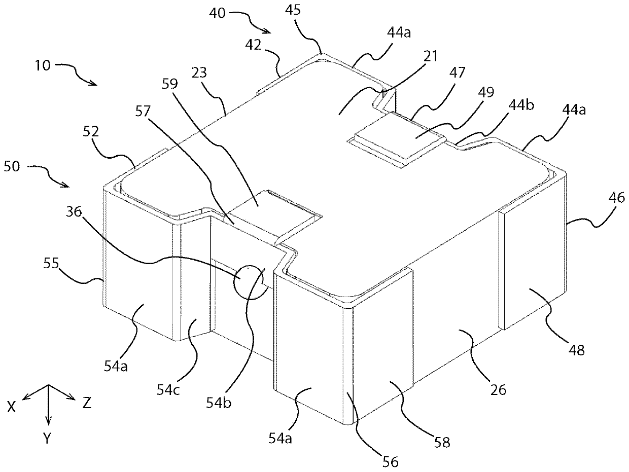
The present invention provides a coil component that has good impact resistance and heat dissipation characteristics and can be applied to high-density mounting. The coil component has a composite magnetic body portion including a magnetic powder and a resin; a coil portion having a winding portion embedded in the composite magnetic body portion; a first metal electrode which is electrically connected to one end portion of the coil portion; a second metal electrode which is electrically connected to the other end portion of the coil portion; the composite magnetic body portion includes a firstsurface and a second surface facing each other, a third surface connecting the first surface and the second surface, a fourth surface and a fifth surface facing each other with the third surface interposed therebetween; the first metal electrode has a first mounting portion provided on the third surface and a first side portion provided on the fourth surface, and the second metal electrode has asecond mounting portion provided on the third surface and a second side portion provided on the fifth surface.

Description

technical field [0001] The present invention relates to a coil component having a composite magnetic body part containing magnetic powder and resin. Background technique [0002] Coil components having a composite magnetic body part including magnetic powder and resin are in high demand in fields requiring miniaturization and high saturation current. For example, small and high-performance coil components are mounted on various devices by high-density mounting on a printed wiring board or the like. [0003] prior art literature [0004] patent documents [0005] Patent Document 1: Japanese Patent Laid-Open No. 2018-22916 [0006] In conventional coil components, problems such as chipping or cracking in the composite magnetic body may occur due to external impact or the like. In addition, reduction in mounting area and improvement in heat dissipation characteristics for realizing high-density mounting are required. Contents of the invention [0007] The present inventi...

Claims


Application Information

Patent Timeline
IPC IPC(8): H01F27/32H01F27/29H01F27/28
CPCH01F27/32H01F27/29H01F27/2876
Inventor 阿部翔平杉本聪
Owner TDK CORPARATION
Why Eureka
Try Eureka