Hand-eye coordination grabbing method based on human eye gaze point

A hand-eye coordination and gaze point technology, which is applied to manipulators, program-controlled manipulators, manufacturing tools, etc., to achieve the effects of convenient operation, accuracy assurance, and efficiency improvement

Active Publication Date: 2019-12-24
HUAZHONG UNIV OF SCI & TECH
12 Cites 3 Cited by

AI-Extracted Technical Summary

Problems solved by technology

Patent US8888287B2 proposes a human-computer interaction system based on a three-dimensional gaze point tracker, which uses a depth camera and an RGB camera to extract gaze direction and gaze...

Method used

S112 sends the grayscale image after smoothing into edge detector (preferably sending into canny edge detector) to obtain edge point, and filter processing to filter out miscellaneous point (namely filter out the edge that obviously does not belong to pupil boundary points) to leave the edge points corresponding to the pupil boundary. Specifically, how to filter, those skilled in the art can design filtering rules according to the needs. I will not go into details here. The remaining edge points corresponding to the pupil boundary are constructed as a pupil edge point set, using the canny edge The detector performs edge detection, with high detection efficiency and high precision;
[0061] Further, the present invention uses lighthouse positioning technology to install positioning marks (infrared receivers) on the eye tracker to achieve higher-precision head posture estimation. The lighthouse positioning technology consists of a lighthouse (infrared generator) and an infrared receiver. The lighthouse is set in the base coordinate system of the manipulator. There are two motors with orthogonal rotation directions inside. The two motors are respectively e...

Abstract

The invention belongs to the technical field of hand-eye coordination, and particularly discloses a hand-eye coordination grabbing method based on a human eye gaze point. The method comprises the steps of S1, determining the human eye gaze point by using an eye movement instrument, and determining the position of an object of interest of a user based on the human eye gaze point; S2, performing discretization traversal to obtain a feasible grabbing gesture set of a mechanical arm at each position in space and storing the feasible grabbing gesture set in a server; S3, accessing a server according to the position of the object of interest of the user so as to query and obtain the feasible grabbing gesture set of the position; S4, obtaining multiple groups of solutions of each joint angle of the mechanical arm based on inverse solutions of each grabbing posture in the feasible grabbing posture set, and determining an optimal solution from the multiple groups of solutions of the joint angles, namely obtaining the optimal joint angle corresponding to each joint of the mechanical arm; and S5, making each joint of the mechanical arm move to the corresponding optimal joint angle, and grabbing the object of interest of the user in the optimal grabbing posture. The method has the advantages of accurate grabbing and convenient operation.

Application Domain

Programme-controlled manipulator

Technology Topic

Arm movingDiscretization +3

Image

  • Hand-eye coordination grabbing method based on human eye gaze point
  • Hand-eye coordination grabbing method based on human eye gaze point
  • Hand-eye coordination grabbing method based on human eye gaze point

Examples

  • Experimental program(1)

Example Embodiment

[0053] In order to make the objectives, technical solutions, and advantages of the present invention clearer, the following further describes the present invention in detail with reference to the accompanying drawings and embodiments. It should be understood that the specific embodiments described here are only used to explain the present invention, but not to limit the present invention. In addition, the technical features involved in the various embodiments of the present invention described below can be combined with each other as long as they do not conflict with each other.
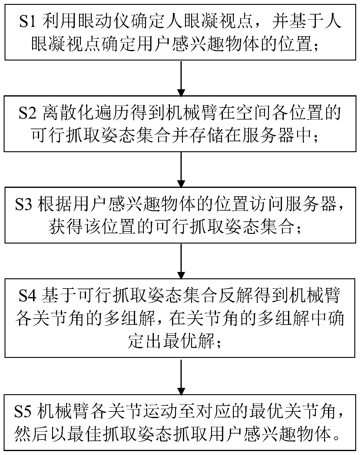
[0054] Such as figure 1 As shown, the embodiment of the present invention provides a hand-eye coordinated grasping method based on the gaze point of the human eye, which includes the following steps:
[0055] S1 uses an eye tracker to determine the gaze point of the human eye, and determines the position of the user's object of interest based on the gaze point of the human eye;
[0056] S2 Discretization traversal obtains a set of feasible grasping postures of the robot arm used to perform grasping actions at various positions in space and stores them in the server;
[0057] S3 accesses the server according to the position of the user's object of interest determined in step S1 to query and obtain a set of feasible grasping postures at that position;
[0058] S4 obtains multiple sets of solutions for each joint angle of the manipulator based on the inverse solution of each grasping pose in the set of feasible grasping poses, and determines the optimal solution from the multiple sets of solutions of joint angles, that is, obtains the optimal joint corresponding to each joint of the manipulator Angle, after determining a set of optimal joint angles, the grasping pose corresponding to the set of joint angles is the best grasping pose;
[0059] Each joint of the S5 robotic arm moves to the corresponding optimal joint angle, and then grabs the user's interested object with the best grasping posture, thereby completing the hand-eye coordinated grasping based on the human eye gaze point.
[0060] Such as Figure 2-3 As shown, the device of the present invention for performing the above method includes a robotic arm 11 and an eye tracker. The robotic arm is fixed on the frame 12 and serves as the right hand (or left hand) of the disabled, and objects to be grasped (bottles, balls, etc.) ) Place in front of the eye tracker. Such as Figure 4 As shown, the eye tracker includes an outer ring main body 3 and a headwear inner ring 2 located inside the outer ring main body 3. The outer ring main body 3 and the headwear inner ring 2 are connected by two moving and rotating parts 9, above the outer ring main body 3 The outer ring upper gusset 8 is provided, and the lower two sides are provided with bracket gusset plates 10. When in use, the eye movement is worn on the human head, the outer ring upper gusset 8 is behind the human head, and the bracket gusset is on the face of the human body. The front; the foreground left camera 4 and the foreground right camera 5 are set on the front side of the outer ring main body 3, and are used to collect the image information of the user's front scene. The left eye camera 6 and the right eye camera 7 are set on the front end of the two bracket gussets. To collect the information of the left and right images of the human eye, a plurality of infrared receivers 1 are evenly distributed on the gusset on the outer ring to receive external infrared rays. The infrared rays are emitted by, for example, an infrared generator located behind the eye tracker. The distance from the eye tracker is preferably more than one meter. When in use, the eye tracker can transmit the data of the foreground left camera 4, foreground right camera 5, left eye camera 6 and right eye camera 7 to the data processing system (computer) through the data cable, and the relevant data of the infrared receiver is sent through wireless Bluetooth To the data processing system (computer) for head posture estimation.
[0061] Further, the present invention adopts lighthouse positioning technology, and installs positioning marks (infrared receivers) on the eye tracker to realize a high-precision head posture estimation. The lighthouse positioning technology consists of a lighthouse (infrared generator) and an infrared receiver. The lighthouse is set in the base coordinate system of the robotic arm. There are two motors with orthogonal rotation directions inside, and linear infrared laser transmitters are installed on the two motors. , Every rotation cycle can sweep all points in the space within the field of view. The infrared receiver is installed on the eye tracker, specifically a set of infrared receiving diodes. When receiving the infrared laser, it can generate response pulses and input them into the data processing system. The lighthouse has a global exposure at the beginning of each rotation cycle, and then the motor takes the linear laser transmitter across the entire space, and each cycle is performed by two orthogonal motors. The infrared receiver on the eye tracker generates a longer-time pulse signal during global exposure, and a shorter-time pulse signal during subsequent laser sweeps. By processing these pulse signals, the time difference between the global exposure and the laser scanning to a certain infrared receiver can be obtained. It is assumed that the scanning time difference between the horizontal and vertical rotation of the i-th receiver is Δt. i1 , Δt i2 , Since the motor speed r is known, the sweep angle of the horizontal and vertical motors can be further calculated:
[0062]
[0063] Furthermore, the 2D point coordinates of each infrared receiver on the virtual plane of the lighthouse can be expressed as:
[0064]
[0065] At the same time, the 3D point coordinates P of each infrared receiver in the eye tracker coordinate system i =(X i ,Y i ,Z i ), which can be obtained from the design parameters of the outer ring body;
[0066] The movement of 3D to 2D point pairs is a PnP problem, which can be solved by direct linear transformation:
[0067] sx i =[R|t]P i
[0068] Among them, s is the amplification factor, x i =(u i ,v i ,1) T , Is the normalized planar homogeneous coordinate representation of the feature point, R and t respectively represent the 3×3 rotation matrix and the 3×1 translation vector, P i =(X i ,Y i ,Z i ,1) T , Is the homogeneous coordinates of the space points corresponding to the feature points. Each set of point pairs provides two linear constraints. [R|t] has a total of 12 dimensions. At least 6 pairs of matching points can solve the transformation.
[0069] The foreground left camera 4 and the foreground right camera 5 are binocular cameras, which are fixed on the front of the outer ring body through the mounting hole. The two foreground cameras can collect the image information of the scene in front of the user, and identify the target object through the target recognition algorithm, and then through the binocular 3D The reconstruction algorithm obtains the three-dimensional coordinates of the target object. The left-eye camera 6 and the right-eye camera 7 use two infrared cameras, which are fixed on the front end of the bracket gusset 10, located under the outer ring main body 3. By adjusting the two bracket gussets 10, the left-eye camera 6 and the right-eye camera 7 can be made Aim at the user’s left and right eyes. There is an infrared light source on the outside of the camera. When the infrared light source is close to the optical axis of the camera, a dark pupil effect will occur, that is, the color of the pupil area in the infrared camera image becomes darker, and the color of the iris and other areas become lighter. , Is conducive to the extraction of pupils.
[0070] Specifically, step S1 includes the following sub-steps:
[0071] S11 uses the left-eye camera 6 and the right-eye camera 7 on the eye tracker to respectively identify the center of the left and right pupils of the user, so as to extract the information of the human eye;
[0072] S12 maps the left and right pupil centers obtained by identification to the foreground left camera 4 to obtain a two-dimensional gaze point;
[0073] S13 extracts the object anchor frame in the foreground left camera, and then determines the object of interest to the user according to the positional relationship between the two-dimensional gaze point and the object anchor frame;
[0074] S14 Perform three-dimensional reconstruction on the object of interest to obtain the position of the object of interest in the foreground left camera 4. The existing conventional posture estimation method can also be used to estimate the posture of the object of interest to obtain the object of interest in the foreground left. Posture in camera 4;
[0075] S15 converts the position of the object of interest in the foreground left camera to the base coordinate system of the robot arm to determine the position of the object of interest to the user.
[0076] Further, step S11 includes the following sub-steps:
[0077] S111 collects the images taken by the left-eye camera 6 and the right-eye camera 7 respectively and performs smoothing processing to obtain a smoothed grayscale image, wherein the smoothing processing is grayscale and filtering operations;
[0078] S112 Send the smoothed gray image to the edge detector (preferably into the canny edge detector) to obtain the edge points, and perform filtering processing to filter out the noise (that is, filter out the edge points that are obviously not the boundary of the pupil). The edge points corresponding to the lower pupil boundary, specifically how to filter, can be designed by those skilled in the art according to their needs. I will not go into details here. The remaining edge points corresponding to the pupil boundary are constructed as the pupil edge point set, which is performed by the canny edge detector. Edge detection, high detection efficiency and high precision;
[0079] S113 performs ellipse fitting on the edge points corresponding to the remaining pupil boundary after filtering to obtain the coordinates of the left and right pupil centers (x l ,y l ) And (x r ,y r ), it is preferable to use the random sampling consensus algorithm to perform ellipse fitting on the edge points corresponding to the pupil boundary to obtain the coordinates of the left and right pupil centers (x l ,y l ) And (x r ,y r ), the parameter equation of the ellipse knows that there are 5 free variables. Therefore, when the random sampling consensus algorithm is used for ellipse fitting, at least 5 edge points are required to fit the parameter equation of the ellipse. In order to obtain the best fitting Close ellipse, random sampling consistency adopts iterative method, the specific steps are as follows:
[0080] S1131 randomly selects 5 points from the pupil edge points to fit the plane parameter equation of the ellipse. The plane parameter equation of the ellipse is:
[0081] Q(x,y)=Ax 2 +Bxy+Cy 2 +Dx+Ey+F
[0082] In the formula, A~F are the coefficients to be calculated;
[0083] S1132 calculates the support function values ​​from all inner points to the ellipse in the pupil edge point concentration. Specifically, the inner points are defined as:
[0084] inliers={(x,y)|error(Q,x,y)
[0085] Where It is the loss function, α is the normalization coefficient, and ε is the preset value, which can be selected according to actual needs, for example, 0.5;
[0086] The support function is defined as: Substituting the inner point corresponding to the ellipse into the following formula to calculate the support function value from the inner point to the ellipse:
[0087]
[0088] In the formula, a and b are the major axis and minor axis of the ellipse, Is the gray gradient of the point (x, y); according to the definition of the support function, the ratio of the short axis to the long axis The larger is, or the gray gradient direction at the inner point of the image is closer to the normal direction at the inner point of the ellipse family (ie The larger), the higher the support function value;
[0089] S1133 repeats steps S1131 to S1132 for a preset number of times (for example, 20 times) to fit multiple ellipses, select the ellipse corresponding to the maximum support function value, and the center of the ellipse is the pupil center.
[0090] Furthermore, a commonly used algorithm in the prior art, such as a polynomial fitting method, can be used to map the identified pupil center to the foreground left camera to obtain a two-dimensional gaze point. The present invention preferably uses a Gaussian process regression algorithm to calculate the coordinates of the pupil center (x l ,y l ) And (x r ,y r ) Is mapped to the foreground camera to get the gaze point (x s ,y s ), specifically, the Gaussian process is a set of any finite random variable with a joint Gaussian distribution. The basic principle is to construct a training set before prediction. The training set includes a series of left and right pupil center coordinates and the corresponding left camera in the foreground. The coordinates of the gaze point on the above, the data in the training set are collected in advance, and the four-dimensional vector (that is, the test point x * ), calculate K(X,X), K(x * ,X), and then substituted into the expected value calculation formula to obtain the expected value, which is the corresponding gaze point (x s ,y s ), specifically, its mathematical model is:
[0091]
[0092] Among them, f is the set of coordinates of the gaze point on the left camera of the foreground in the training set, and X is the set of input vector x, where the input vector is a 4-dimensional vector x=(x l ,y l ,x r ,y r ), K(X,X) is the symmetric positive definite covariance matrix of the training set, K(x * ,X) is the actual measured x * N×1 covariance matrix with training set X, k(x * ,x * ) Is the covariance of the test point itself, and the expected value of the predicted value is:
[0093]
[0094] among them, Is the expected value, which is the predicted value of the gaze point in the foreground camera obtained through Gaussian process regression (x s ,y s ).
[0095] Preferably, step S13 includes the following sub-steps:
[0096] S131 uses the target recognition algorithm to identify the anchor frame of the object in the foreground left camera, such as Figure 5 As shown, the cylinder on the left represents the water glass, and the circle on the right represents the ball. The dotted line containing the water glass and the ball is the anchor frame corresponding to the water glass and the ball. The object anchor frame is used to initialize the tracking target in the tracking algorithm, and the target is recognized The algorithm and the tracking algorithm are carried out simultaneously, and the target recognition algorithm and the tracking algorithm can use the existing conventional methods;
[0097] S132 initializes the tracking algorithm to track the object. If the object is lost, the tracking algorithm is re-initialized using the real-time recognition result of the target recognition algorithm, and then the initialized tracking algorithm is used to continue tracking the object to obtain the anchor frame of the object. , The above method can effectively improve the success rate of object recognition in the foreground left camera;
[0098] S133 then determines the object of interest to the user according to the positional relationship between the two-dimensional gaze point mapped to the left camera in the foreground and the object anchor frame, where, as Figure 5 As shown, if the gaze point falls into the anchor frame of the water cup (such as Figure 5 The black dot located in the anchor frame of the water glass) thinks that the user is interested in the water glass, if the gaze point does not fall into the anchor frame of the water glass (such as Figure 5 The white dot outside the anchor frame of the water glass) thinks that the user is not interested in the water glass; if the gaze point falls into the anchor frame of the ball (such as Figure 5 The black dot located in the anchor box of the ball in the middle) thinks that the user is interested in the ball. If the gaze point does not fall into the anchor box of the ball (such as Figure 5 The white dot outside the anchor box of the ball) thinks that the user is not interested in the ball.
[0099] Preferably, in step S14, the three-dimensional reconstruction of the object of interest to the user specifically includes:
[0100] S141 obtains the internal and external parameters of the foreground left camera and the foreground right camera through dual target determination, specifically including the internal parameter matrix and external parameter matrix of the foreground left and right cameras, and derives the reprojection matrix Q through the internal and external parameter matrix;
[0101] S142 uses the internal and external parameters of the binocular camera to correct and align the images in the foreground left camera and the foreground right camera, which is a prior art and will not be repeated here;
[0102] S143 obtains the binocular disparity value d of the image pixels of the foreground left camera and the foreground right camera through the feature matching algorithm. Preferably, the feature matching adopts the normalized cross-correlation method, and the correlation measurement method is:
[0103]
[0104] Among them, p(x,y) represents the coordinates of any point in the foreground left camera, W p Represents the rectangular area centered at p, L(x,y) represents the gray value at the point (x,y) in the foreground left camera image, Represents W in the foreground left camera image p The mean gray value of R(x+d,y) represents the gray value at the point (x+d,y) in the right camera image of the foreground, Represents the average gray value in the rectangular area corresponding to the point (x+d,y) in the foreground right camera image, and the d that maximizes the correlation in the above formula is the binocular disparity value;
[0105] S144 uses the binocular disparity value and the re-projection matrix Q obtained by the dual target to reconstruct the three-dimensional coordinates of each pixel in the foreground left camera image in the foreground left camera coordinate system to complete the three-dimensional reconstruction of the object. The principle is:
[0106] [X Y Z W] T =Q*[x y d 1] T
[0107] Among them, [X Y Z W] are the homogeneous coordinates in the foreground left camera coordinate system, and (x, y) are the two-dimensional coordinates in the foreground left camera image coordinate system.
[0108] More specifically, step S15 preferably adopts the following steps to convert the position of the object of interest in the foreground left camera to the base coordinate system of the robotic arm:
[0109] S151 uses multiple infrared receivers on the eye tracker in combination with the infrared generator (ie lighthouse) located in the base coordinate system of the robotic arm to obtain the transformation matrix of the coordinate system of the eye tracker relative to the base coordinate system of the robotic arm, which specifically includes:
[0110] S1511 measured the 2D coordinates of each infrared receiver on the virtual plane of the infrared generator (u i ,v i ):
[0111]
[0112] Where α i In order to drive the horizontal rotation of the infrared generator, the horizontal sweep angle of the motor, β i The sweep angle in the vertical direction of the motor that drives the infrared generator to rotate vertically;
[0113] S1512 uses the following formula to perform direct linear transformation to obtain the transformation matrix [R|t] of the eye tracker coordinate system relative to the robot arm base coordinate system:
[0114] sx i =[R|t]P i
[0115] The above formula is the method of solving 3D to 2D point pair motion (PnP problem), where s is the magnification factor, x i =(u i ,v i ,1) T , R and t denote 3×3 rotation matrix and 3×1 translation vector, respectively, P i =(X i ,Y i ,Z i ,1) T , (X i ,Y i ,Z i ) Represents the 3D coordinates of the infrared receiver in the eye tracker coordinate system. Each set of point pairs provides two linear constraints. [R|t] has a total of 12 dimensions, so at least 6 pairs of matching points can be used to solve the transformation matrix [R| t], so there are more than 6 infrared receivers;
[0116] S152 obtains the transformation matrix between the foreground left camera and the coordinate system of the eye tracker through calibration;
[0117] S153 converts the pose of the object of interest in the foreground left camera to the base coordinate system of the manipulator according to the two transformation matrices.
[0118] In step S2, the discretization traversal to obtain the feasible grasping posture of the robot arm used to perform the grasping action at each position in space refers to the discretization to obtain the reachable positions of the robot arm in its working space, and then the discretization to obtain The set of feasible grasping postures corresponding to each position point.
[0119] In a preferred embodiment, the discretization method of position points is:
[0120] The maximum distance between the end of the robotic arm and the shoulder joint of the robotic arm is r, the volume of the sphere with this radius The discrete sampling interval of the three axes is d (which is set according to the size of the object to be grasped), so the number of sampling points (ie, the number of position points) in the entire robotic arm workspace is N=V/d 3.
[0121] The discretization method of grasping posture is:
[0122] Divide the attitude angle equally by 0.255 radians, then the number of attitude samples at one point (that is, the grasping attitude) is 576. Use the IKfast reverse solution toolkit to determine the attitude solvability corresponding to each position point, and establish the reachability of the mechanical part Spatial database:
[0123]
[0124] Where p i Is the i-th position point, the upper limit of i is N=V/d 3 , Means p i The solvable pose set of a point, the upper limit M is determined by p i The number of solvable poses of the point is determined, and the maximum value is 576. Generally, there are many solvable postures in front of the manipulator base, and the maximum number of solvable postures reaches 94/576, while there are fewer solvable postures at the edge of the working space.
[0125] In step S4, the kinematics inverse solution module is specifically used to obtain the joint angles of the manipulator based on the inverse solution of the grasping posture. Preferably, the IK fast inverse solution module is used. The problems solved by the inverse solution module are as follows:
[0126]
[0127] among them, Is the end effector of the robotic arm (manipulator) coordinate system O 8 To the robot arm base coordinate system O 0 The transformation matrix between (that represents the pose of the end effector), Is the robot arm end effector coordinate system O 8 To the end coordinate system of the second link of the robotic arm O 7 Constant transformation matrix between, where, i=1,2,...,7 is the link transformation corresponding to the seven joints of the robotic arm, such as Image 6 As shown, the coordinate system O i Is the joint angle θ i The coordinate system where it is located, coordinate system O 8 Not present Image 6 Marked in, because the coordinate system O 8 It is a required posture, it is a multi-solution, Image 6 Where d(se) and d(ew) are the lengths of the first link of the robotic arm and the second link of the robotic arm, respectively, the lengths are 329.2mm and 255.5mm respectively; the vectors n, o, a and p are the end of the robotic arm, respectively Actuator coordinate system O 8 In the robot arm base coordinate system O 0 The following pose vector (ie grasping pose) and position vector (ie target position, that is, the position of the object of interest to the user). Through the above formula (1), each transformation matrix can be solved, namely Then use The inverse solution of the following formula (2) is used to obtain the joint angles of the robotic arm:
[0128]
[0129] Among them, c is the abbreviation of cos, θ i Is the i-th joint angle, s is the abbreviation of sin, a i-1 For along X i-1 Axis from Z i-1 Move to Z i Distance, α i-1 To go around X i-1 Axis from Z i-1 Rotate to Z i Angle, d i For along Z i Axis from X i-1 Move to X i Distance, X i Is the coordinate system O i X axis, Z i Is the coordinate system O i Z axis, see Image 6 , Image 6 The parameters in are shown in Table 1.
[0130] Table 1
[0131]
[0132] Specifically, the mechanical arm used in the present invention contains 7 degrees of freedom and one redundant degree of freedom. In the working space, its kinematics inverse solution may have an infinite number of groups (that is, more than one can be solved by formula (2)). Group joint angles, each group of joint angles contains 7 joint angles, namely θ 1 ~θ 7 ), therefore, set certain rules according to the actual situation to find the optimal set of solutions. The inverse solution of robot kinematics generally follows the shortest stroke principle, which means that the amount of movement of each joint is minimized. At the same time, the general mechanical arm is a tandem mechanism. A small rotation of the shoulder joint will have a great impact on the position of the end wrist joint. , So it should be weighted, that is, move the end joints more and move the front joints less. Based on this, the present invention uses maximizing the sum of the relative angle margins of all joints as the optimization criterion to find the optimal set of joint angles:
[0133]
[0134] Where θ={θ i },i = 1...7, that is, the farther away each joint angle is from the limit position, the better, so that the flexibility of the joint angle is higher and less limited by the joint range.
[0135] The optimization objective of formula (1) is not convenient for optimization, and can be equivalent to minimizing the mean value of the absolute value of the relative angle deviation, namely:
[0136]
[0137] Among them, μ=mean(aad) is the mean value of the absolute value of the relative angle deviation, and the absolute value of the relative angle deviation aad is expressed as:
[0138]
[0139] At the same time, in order to prevent large deviations in individual joint angles, the standard deviation can be added to the optimization function, so the optimization objective function becomes:
[0140]
[0141] Among them, σ=var(aad) is the variance of the absolute value of the relative angular deviation.
[0142] In actual operation, when the above-mentioned method is used to realize the grasping of the object, there is still a certain error. In order to improve the accuracy of grasping, the present invention preferably performs compensation processing. Specifically, calculating the execution error of each joint angle after step S4 includes:
[0143] First, obtain the pre-grabbing position according to the position of the user's object of interest and the determined optimal grasping posture and deviating from the preset offset distance in the reverse direction of the grasping, and access the server to query the feasible grasping posture of the pre-grabbing position Set; specifically, the position of the object of interest to the user is c, and the pre-grabbing position is p=c+z R ·B, where z R Is the main axis vector of the manipulator in the best grasping posture (the direction perpendicular to the palm center), b is the preset offset distance, preferably set to 10cm;
[0144] Then, based on the inverse solution of each grasping posture in the set of feasible grasping postures, multiple sets of solutions of each joint angle of the manipulator are obtained, and the optimal solution, namely the target joint angle, is determined from the multiple sets of solutions of joint angles;
[0145] Next, move each joint of the robot arm to the corresponding target joint angle, and then measure the position of the end of the robot arm and inversely solve to obtain the real joint angle of each joint of the robot arm, specifically to obtain the real rotation angles of the 1-5 joints of the robot arm. The tracker (tracker) fixed on the forearm of the robot arm (the second link) is used to measure the position of the end of the robot arm: the tracker on the forearm of the robot arm can get the tracker coordinate system relative to the robot base coordinate system Transformation matrix And the tracker is set on the forearm, so the wrist joint (the end of the second link) coordinate system O 5 The transformation matrix to the tracker coordinate system It can be obtained by one calibration, so the wrist coordinate system O can be obtained 5 To the base coordinate system of the robot arm (i.e. coordinate system O 0 ) Transformation Then use the kinematics inverse solver IK fast to solve the following formula, which can be inverted to obtain the least square solution (overdetermined solution) of the first 5 joints as the actual rotation angle
[0146]
[0147] Finally, calculate the difference between the target joint angle and the real joint angle to obtain the execution error of each joint of the manipulator, that is, use the difference between the target rotation angle and the corresponding actual rotation angle to obtain the execution error of the first five joints, and then use each execution error to obtain step S4 Compensation for each optimal joint angle of each optimal joint angle, that is, each optimal joint angle plus the corresponding execution error to obtain the compensated joint angle. Finally, in step S5, each joint of the manipulator is moved to the corresponding compensated joint angle. Ensure that the actual position reached by the robotic arm is the target position (that is, the position of the user's object of interest) to achieve high-precision grasping.
[0148] The invention can accurately locate the object that the user observes (interest), and control the end of the robotic arm to reach the position of the object in a anthropomorphic manner. The anthropomorphic manipulator can grab the object of interest and perform specified actions, such as drinking water and carrying a small ball, It can help patients with severe physical disabilities grasp objects of interest.
[0149] Those skilled in the art can easily understand that the above descriptions are only preferred embodiments of the present invention and are not intended to limit the present invention. Any modification, equivalent replacement and improvement, etc. made within the spirit and principle of the present invention, All should be included in the protection scope of the present invention.

PUM

no PUM

Description & Claims & Application Information

We can also present the details of the Description, Claims and Application information to help users get a comprehensive understanding of the technical details of the patent, such as background art, summary of invention, brief description of drawings, description of embodiments, and other original content. On the other hand, users can also determine the specific scope of protection of the technology through the list of claims; as well as understand the changes in the life cycle of the technology with the presentation of the patent timeline. Login to view more.

Similar technology patents

Clamping claw type manipulator device with closing cover

ActiveCN105500398AGuaranteed reliabilityaccurate capture
Owner:ZHEJIANG RUIFENG MACHINERY EQUIP

Fan-shaped seedling taking and placing device

ActiveCN112340443Aaccurate capturesave vertical space
Owner:广西桂康元农业科技有限公司

New system satellite signal NH code stripping method

ActiveCN109884673Aaccurate captureAccurate capture results
Owner:BEIJING AUTOMATION CONTROL EQUIP INST

Insect catching net

PendingCN111528203Aaccurate captureeasy to carry
Owner:SOUTHWEST FORESTRY UNIVERSITY

Hoisting and transporting mechanism and cargo transporting method

PendingCN112850578Aaccurate capturelabor saving
Owner:XI'AN UNIVERSITY OF ARCHITECTURE AND TECHNOLOGY

Classification and recommendation of technical efficacy words

  • accurate capture
  • easy to operate

Columnar material arranging and stacking pipeline system

ActiveCN103241545Aaccurate captureaccelerate
Owner:SHENZHEN KING EXPLORER SCI & TECH CORP

Method for selecting flow refining marketing parameters

InactiveCN104766221AImprove classification accuracyaccurate capture
Owner:HUADI COMP GROUP

Theme mining and behavior analysis method for video moving target

ActiveCN112347879Aaccurate capture
Owner:CHINASO INFORMATION TECH

New system satellite signal NH code stripping method

ActiveCN109884673Aaccurate captureAccurate capture results
Owner:BEIJING AUTOMATION CONTROL EQUIP INST

Lancet device

InactiveUS7303573B2inexpensively mass-producedeasy to operate
Owner:ABBOTT DIABETES CARE INC

Rapid and non-invasive optical detection of internal bleeding

InactiveUS20050065436A1easy to operaterapid and accurate result
Owner:HO WINSTON ZONH +2
Why Eureka
Try Eureka