Method for detecting heat source center in three-dimensional space
A three-dimensional space, center detection technology, applied in the field of computer vision, can solve problems such as large amount of calculation and expensive equipment
- Summary
- Abstract
- Description
- Claims
- Application Information
AI Technical Summary
Problems solved by technology
Method used
Image

Examples
Embodiment Construction
[0032] In order to make the purpose, technical solution and advantages of the present invention more clear, the specific implementation of the present invention will be further described below in conjunction with the accompanying drawings, but the method of the present invention is not limited.
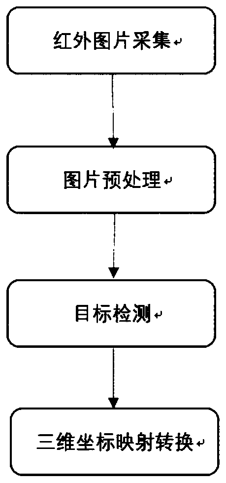
[0033] attached figure 1 It is the main flow chart of the method of the present invention, and the overall scheme is infrared image preprocessing, target detection of two-dimensional images, conversion of two-dimensional coordinates to three-dimensional coordinates. The specific steps are as follows:
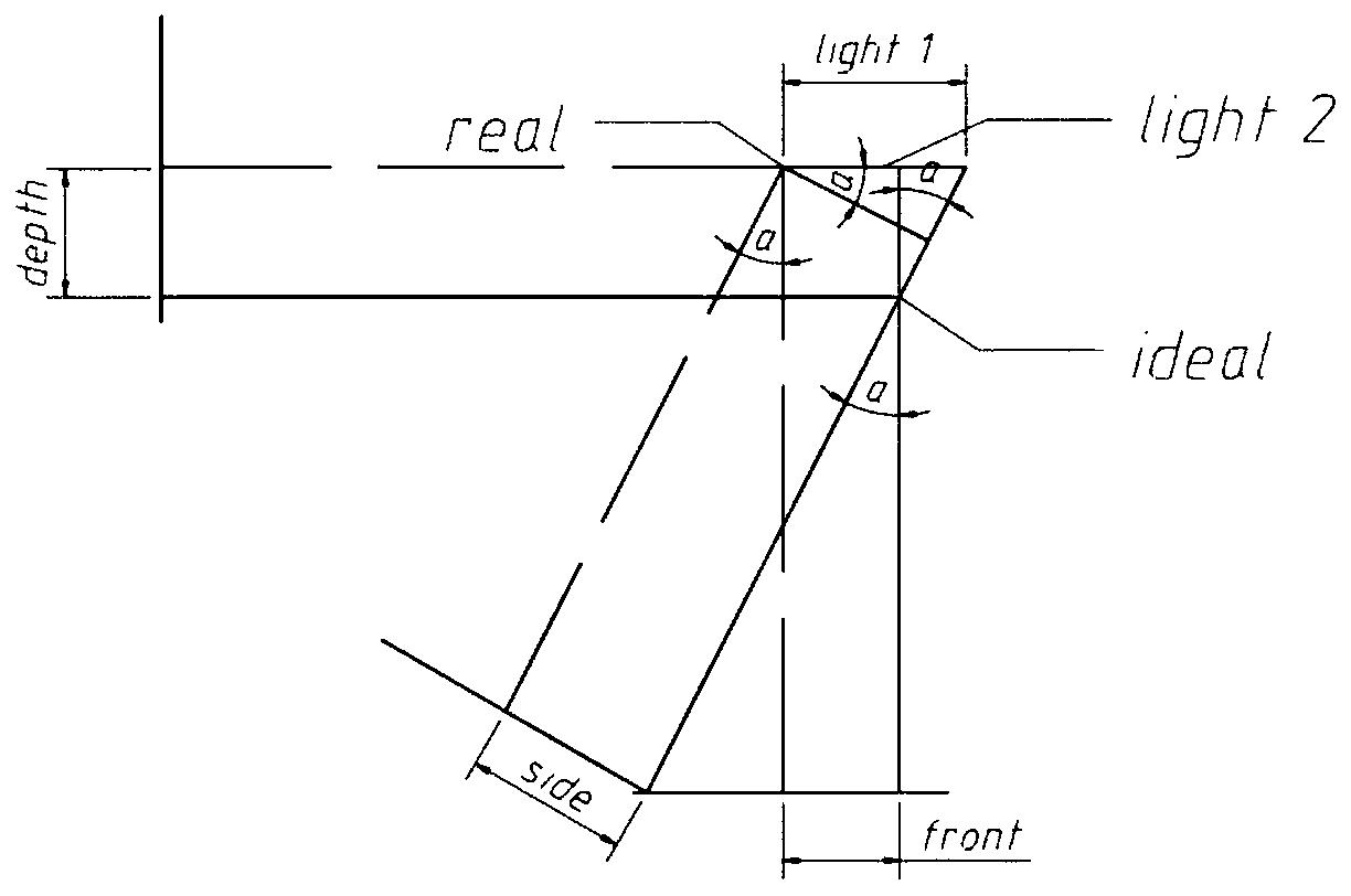
[0034] (1) Calibrate the ideal space center as the origin of the space coordinates, and use this to rotate two angles arbitrarily, take an infrared picture at each of these two positions, and then extract the R channel values of the two infrared pictures to obtain a new picture, Then cut the new picture according to small squares of a certain size, and calculate the average value of ...
PUM
 Abstract
Description
Claims
Application Information
 - R&D
- Intellectual Property
- Life Sciences
- Materials
- Tech Scout
- Unparalleled Data Quality
- Higher Quality Content
- 60% Fewer Hallucinations
Browse by: Latest US Patents, China's latest patents, Technical Efficacy Thesaurus, Application Domain, Technology Topic, Popular Technical Reports.
© 2025 PatSnap. All rights reserved.Legal|Privacy policy|Modern Slavery Act Transparency Statement|Sitemap|About US| Contact US: help@patsnap.com