System and method for finding the direction of a wave source using an array of sensors

a wave source and array technology, applied in the direction of direction finders, radio wave direction/deviation determination systems, instruments, etc., can solve the problems of erroneous direction, two-dimensional space, and difficulty in finding the peak point of maximum signal strength

Inactive Publication Date: 2001-03-06
ANDREA ELECTRONICS CORPORATION
View PDF6 Cites 89 Cited by
  • Summary
  • Abstract
  • Description
  • Claims
  • Application Information

AI Technical Summary

Benefits of technology

Another object of the invention is to provide a system which can estimate the wave-source direction by taking into account the directions measured from individual microphone pairs and combining them to find the best-estimated source

Problems solved by technology

However, the use of beamforming for sound-source direction finding has several drawbacks.
First, a typical beamforming profile of receiving sensitivity over the angles of looking direction is so flat that it is, as a practical matter, difficult to find the peak point of maximum signal strength unless an inconvenience of a large microphone array is used.
As a result, even a slight numerical error or noise may perturb the result, giving an erroneous direction.
Finding the source direction in terms of a horizonal direction (azimuth) and a vertical direction (elevation) involves searching two-dimensional space, which is computationally expensive.
This requires delaying and summing the received signals at a very small delay step, which, in turn, requires that the signal be sampled at a very high sampling rate, imposing a severe computational burden.
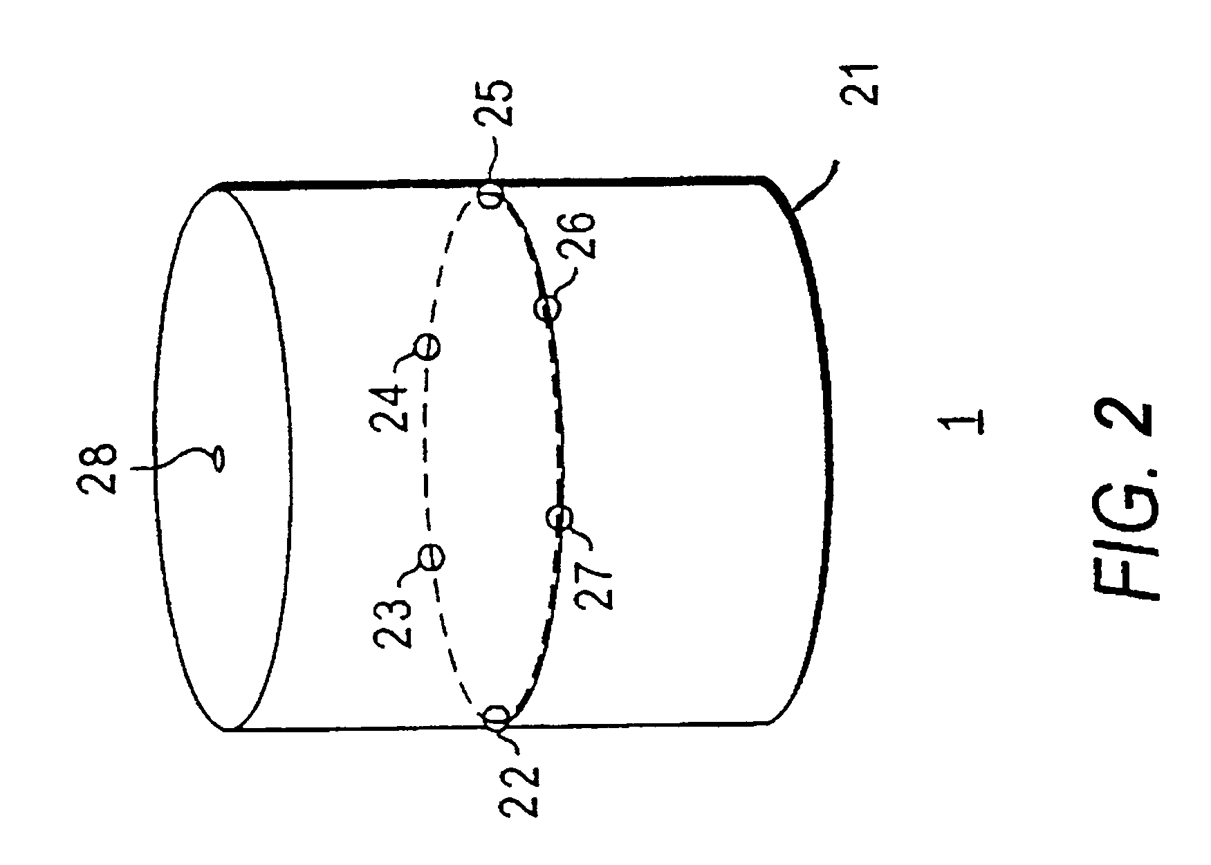
First, since all the microphones are on the same vertical plane, they produce the same delay w

Method used


Image

  • System and method for finding the direction of a wave source using an array of sensors
  • System and method for finding the direction of a wave source using an array of sensors
  • System and method for finding the direction of a wave source using an array of sensors

Examples


first embodiment

FIG. 6a shows the qualification unit that uses a signal-to-noise ratio (SNR) as a measurement criterion. The SNR is defined as a ratio of a signal power to a noise power. To calculate the SNR, the measured signals are divided into blocks of signals having a predetermined period such as 40 milliseconds. Block 61 calculates the signal power for each signal block by calculating the square-sum of the sampled signals within the block. The noise power can be measured in many ways, but one convenient way of measuring the noise power may be to pick the signal power of the signal block having the minimum signal power and to use it as the noise power. Block 62 selects the signal block having the minimum power over a predetermined interval such as 2 second. Block 63 calculates the SNR as the ratio of the signal power of the current block to that of the noise power. Block 64 invalidates the precise direction if the SNR is below a certain threshold.

second embodiment

FIG. 6b shows the measurement qualification unit that uses a spread (range of distribution) of individual measured delays as a measurement criterion. The precise source direction calculated by the precise-direction finder represents an average direction among the individual measured directions measured by microphone pairs in the sector. Since delays are directly related to direction angles, the spread of the individual measured delays with respect to the individual estimated delay indicates how widely the individual directions vary with respect to the precise direction. Thus, the spread gives a good indication as to the validity of the measurements. For example, if the individual measured delays are too widely spread, it is likely to indicate some kind of measurement error.

T.sub.e is defined as a vector representing the set of individual estimated delays .tau..sub.e corresponding to the precise direction, K. Block 71 calculates T.sub.e from K based on the linear relation between K a...

third embodiment

FIG. 6c shows the measurement qualification unit that uses the azimuth angle, .phi., as a measurement criterion. If .phi. deviates significantly from the sector direction (the approximate source direction), it is likely to indicate that the precise direction is false. Therefore, if .phi. is not within a permissible range of angles (e.g. within + / -60 degrees) of the sector direction, the precise direction is invalidated.


PUM


Abstract

A system and method for finding the direction of a wave source using an array of sensors. The system includes a sensor array for measuring waves from the wave source, an approximate-direction finder for finding the approximate direction of the wave source in terms of a sensor pair from the sensors, a precise-direction finder for finding the precise direction of the wave source based on the approximate direction found, and a measurement qualification unit for evaluating the validity of the precise direction under a measurement criterion and discarding the measurements if the criterion is not met.

Description

1. FIELD OF THE INVENTIONThe present invention relates generally to signal processing, and more specifically to a system and method using signal processing for finding the direction of a particular wave source using an array of sensors.2. BACKGROUND OF THE INVENTIONA system for finding or tracking the direction of a particular wave source has many applications. One example is a directional microphone system, where a microphone is to be pointed to the direction of a particular sound source. Another is a video conferencing system, where a camera needs to be moved to the direction of the participating speaker.One well-known technique of wave-source direction finding is beamforming. Beamforming, itself well-known in the art, uses an array of sensors located at different points in space. Connected to the array of sensors is a spatial filter that combines the signals received from the sensors in a particular way so as to either enhance or suppress signals coming from certain directions re...

Claims


Application Information

Patent Timeline
IPC IPC(8): G01S3/00G01S3/808G01S3/802G01S3/14G01S7/02
CPCG01S3/8083
Inventor MARASH, JOSEPH
Owner ANDREA ELECTRONICS CORPORATION
Why Eureka
Try Eureka