Method and device for wireless communication using MIMO techniques

a wireless communication and mimo technology, applied in the direction of radio transmission, transmission, electrically long antennas, etc., can solve the problems of 2 sided svd degradation, inability to rapidly change channels, outdated and/or inaccurate, etc., to achieve the effect of reducing the cost of circuitry and computational complexity, computation complexity, and reducing the cost of circuitry

Inactive Publication Date: 2009-06-04
QUALCOMM INC
View PDF2 Cites 92 Cited by
  • Summary
  • Abstract
  • Description
  • Claims
  • Application Information

AI Technical Summary

Benefits of technology

[0013]The present invention describes a method of closed loop MIMO communication utilizing implicit or explicit channel state information (CSI) at the transmitter and the receiver. The transmitter performs unitary linear pre-processing of given input signals and the receiver further mitigates the mutual interference between the streams by performing MMSE processing on the received signals. The MMSE matrix is computed with respect to the transmitter-processed channel. The resulting throughput comes close to the optimum (realized by the SVD scheme). This is accomplished without the expensive circuitry and computational complexity required by a full SVD solution. In addition, this method has increased stability amid channel fluctuations and channel estimation's noise. One preferred embodiment of the present invention provides a MIMO communication method that includes the following steps. The transmitter performs non-SVD decomposition of a channel matrix to a product that includes a unitary matrix (or matrices) and a first processed channel matrix. The transmitter then transmits pilot and data signals multiplied by one or more of these calculated unitary matrices. In the next step, the receiver utilizes the pilot signals to estimate the composite channel and processes the data signals by an MMSE filter formed from this estimated channel. The resulting final [i.e. post MMSE] effective channel-matrix has (statistically) enhanced diagonal with respect to Frobenius norm. When the transmitter and the receiver switch roles, the approximated CSI becomes available to the current transmitter via the above mentioned pilot signals. According to various embodiments of the invention, the first processed channel matrix can be a general triangular matrix (following QR decomposition), or a bi-diagonal matrix (following bi-diagonal decomposition), which is a triangular matrix with two non zero diagonals. Another embodiment utilizes Jacobi rotations to increase the diagonal mass (measured by Frebenius norms) of the first processed channel matrix, thus increasing the strength of the desired signal and reducing interference. Application of Jacobi rotations can be in a stand-alone mode or as enhancement to other embodiments, and is performed to the extent that computational resources permit. In another embodiment, the transmitter computes SVD periodically, on a subset of the frequency sub-carriers, resulting in a diagonal matrix (i.e. triangular matrix with values concentrated on the main diagonal). The preprocessing capabilities are then enhanced in the rest of the sub-carriers by combining the SVD with QR decomposition or Jacobi rotations.
[0014]SVD computation becomes more efficient by another aspect of the invention that enables a smaller search window of the related eigenvalues.
[0015]In summary, the premise of the present invention is that an optimal transmission scheme, based on SVD, is an expensive asset whose circuitry and utilization should be avoided or minimized. The invention thus provides a low cost, high-performance robust alternatives in which the transmitter carries out a QR or bi-diagonalization and / or Jacobi rotations and / or sporadic SVD's and the receiver performs MMSE on the resulting processed channel.

Problems solved by technology

However, its formidable complexity and high sensitivity to channel fluctuations and estimation errors make it impractical for rapidly varying channels and call for alternative solutions.
Their approach is particularly suitable when the communication channel varies over time and frequency and, due to channel estimation limitations, 2 sided SVD shows degradation in performance.
This patent treats the realistic situation where, even when CSI exists, it might be outdated and / or inaccurate due to channel estimation corruption.

Method used


Image

  • Method and device for wireless communication using MIMO techniques
  • Method and device for wireless communication using MIMO techniques
  • Method and device for wireless communication using MIMO techniques

Examples


Embodiment Construction

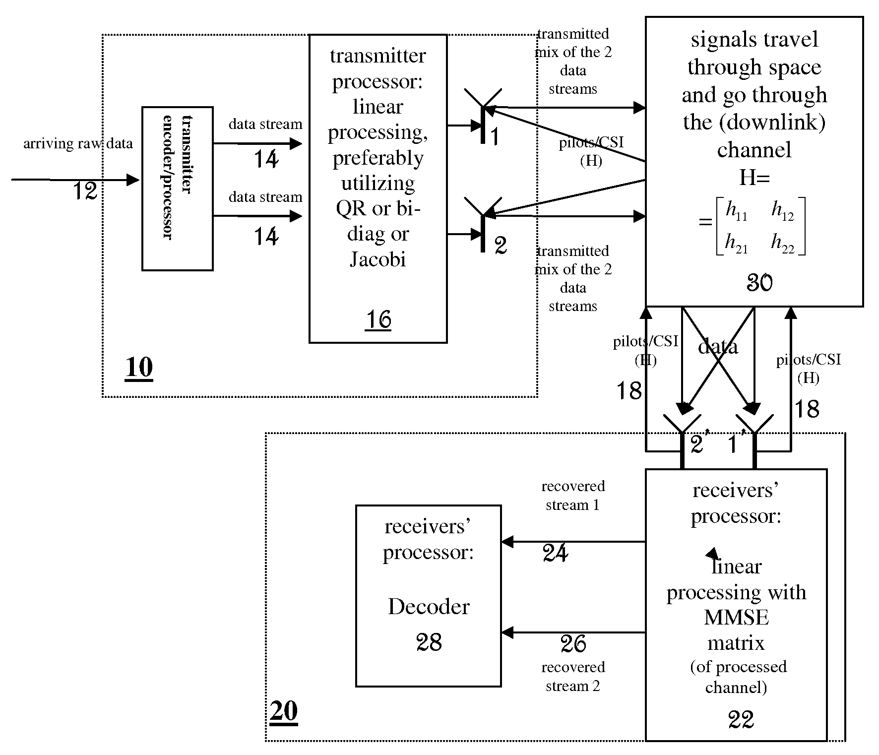
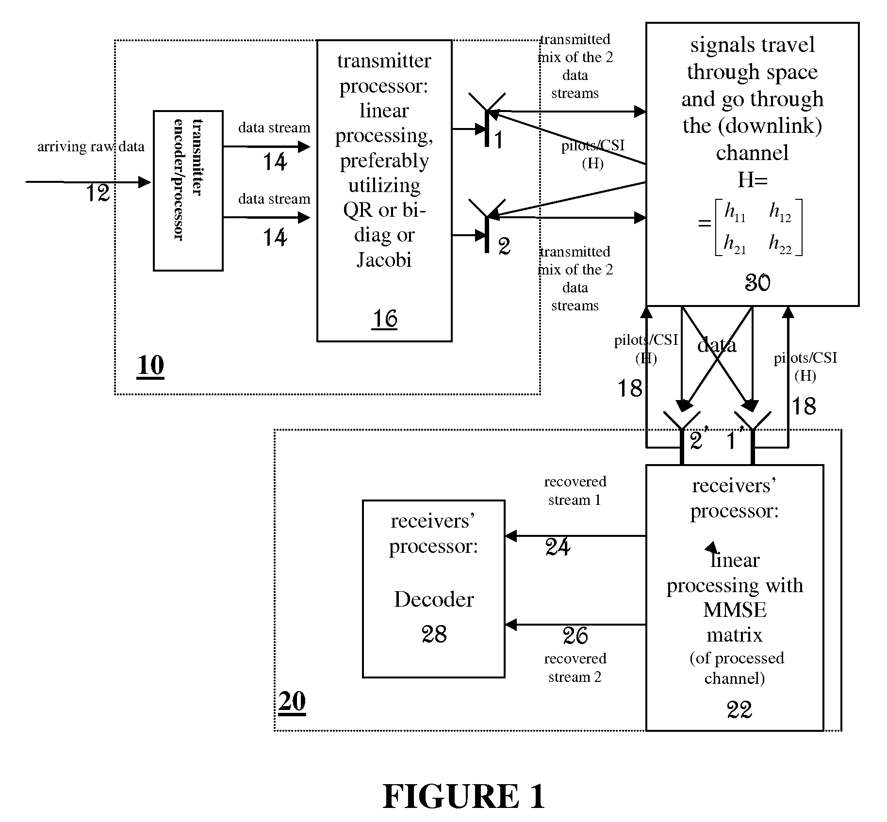
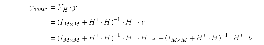
[0018]The present invention relates to a closed loop MIMO wireless communication technique and device. It provides performance close to that of the optimal SVD, with much less cost in circuitry and calculations. This is accomplished by simplified transmitter's linear pre-processing of the data to be transmitted. The matrix used for this linear pre-processing is a unitary matrix obtained through decomposition of the channel matrix. While the resulting effective channel matrix is typically non-diagonal, its diagonal is statistically enhanced with respect to Frobenius norm. The receiver performs MMSE on the received signals to further mitigate the interference between MIMO streams. The corresponding MMSE matrix is computed by the receiver with respect to the processed channel. It will be appreciated that although this scheme has sub-optimal performance, it is significantly more practical than the optimal SVD scheme. This technique is useful in particular in LTE and WiMAX networks havin...


PUM


Abstract

The present invention describes a method of closed loop MIMO communication utilizing implicit or explicit channel state information (CSI) at the transmitter and the receiver. The transmitter performs linear pre-processing (for example, QR decomposition or bi-diagonal decomposition or Jacobi rotations, and/or sporadic SVDs) on a channel matrix, and the receiver mitigates the mutual interference between the streams by performing MMSE processing on the received signals. The MMSE matrix is computed with respect to the processed channel that may estimated by the receiver through preprocessed pilot signals. The transmitters preprocessing is of much lesser cost and complexity than full SVD.

Description

FIELD OF THE INVENTION[0001]The present invention relates to wireless communications networks, in general and, in particular, to communications networks utilizing MIMO techniques.BACKGROUND OF THE INVENTION[0002]Multiple-Input Multiple-Output (MIMO) systems utilize multiple antennas at the transmitter and receiver on both sides of a wireless communication channel. This can increase data rates without requiring additional power, by permitting concurrent transmittal of several streams of data, and by performing spatial information processing. MIMO schemes enable the transmitter to transform a data stream to multiple streams and send them through multiple transmit antennas. A multiple antenna receiver processes the received streams and reconstructs the original information. In an ideal network, MIMO capacity increases linearly with the number of antennas at the receiver or at the transmitter, whichever is lower.[0003]In a multi antenna setting, the transmitted signal is linearly transf...

Claims


Application Information

Patent Timeline
Patent Type & Authority Applications(United States)
IPC IPC(8): H04B1/10H04B15/00
CPCH04B7/0417H04B7/0413H04B7/0854H04B7/0634
Inventor BARAK, OZTOUBOUL, ASSAFDOR, AVNER
Owner QUALCOMM INC
Why Eureka
Try Eureka