Connector and plug

A plug and plug housing technology, applied in the direction of connection, two-part connection device, parts of the connection device, etc., can solve problems such as affecting the conduction of contacts, and achieve the effects of improving identification accuracy, increasing strength, and simplifying the overall structure

Pending Publication Date: 2019-12-24
CHINA AVIATION OPTICAL-ELECTRICAL TECH CO LTD
View PDF1 Cites 0 Cited by
  • Summary
  • Abstract
  • Description
  • Claims
  • Application Information

AI Technical Summary

Problems solved by technology

[0005] The purpose of the present invention is to provide a plug, which can solve the problem in the prior art that the connection between the plug and the socket is affected by the oblique insertion; another purpose of the present invention is to provide a connector using the plug, It can ensure the normal conduction of the contacts in the connector when the connector is in use

Method used


Image

  • Connector and plug
  • Connector and plug
  • Connector and plug

Examples


Embodiment Construction

[0041] The specific embodiments of the connector and its plug in the present invention will now be described with reference to the accompanying drawings.

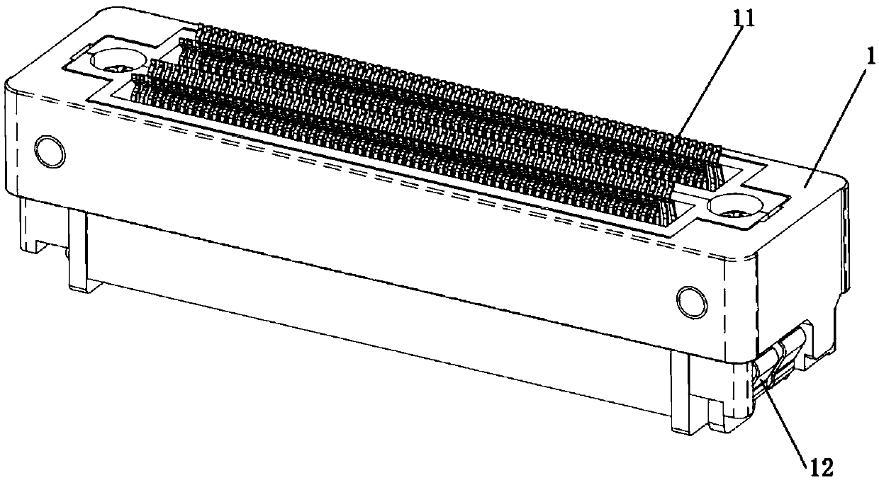
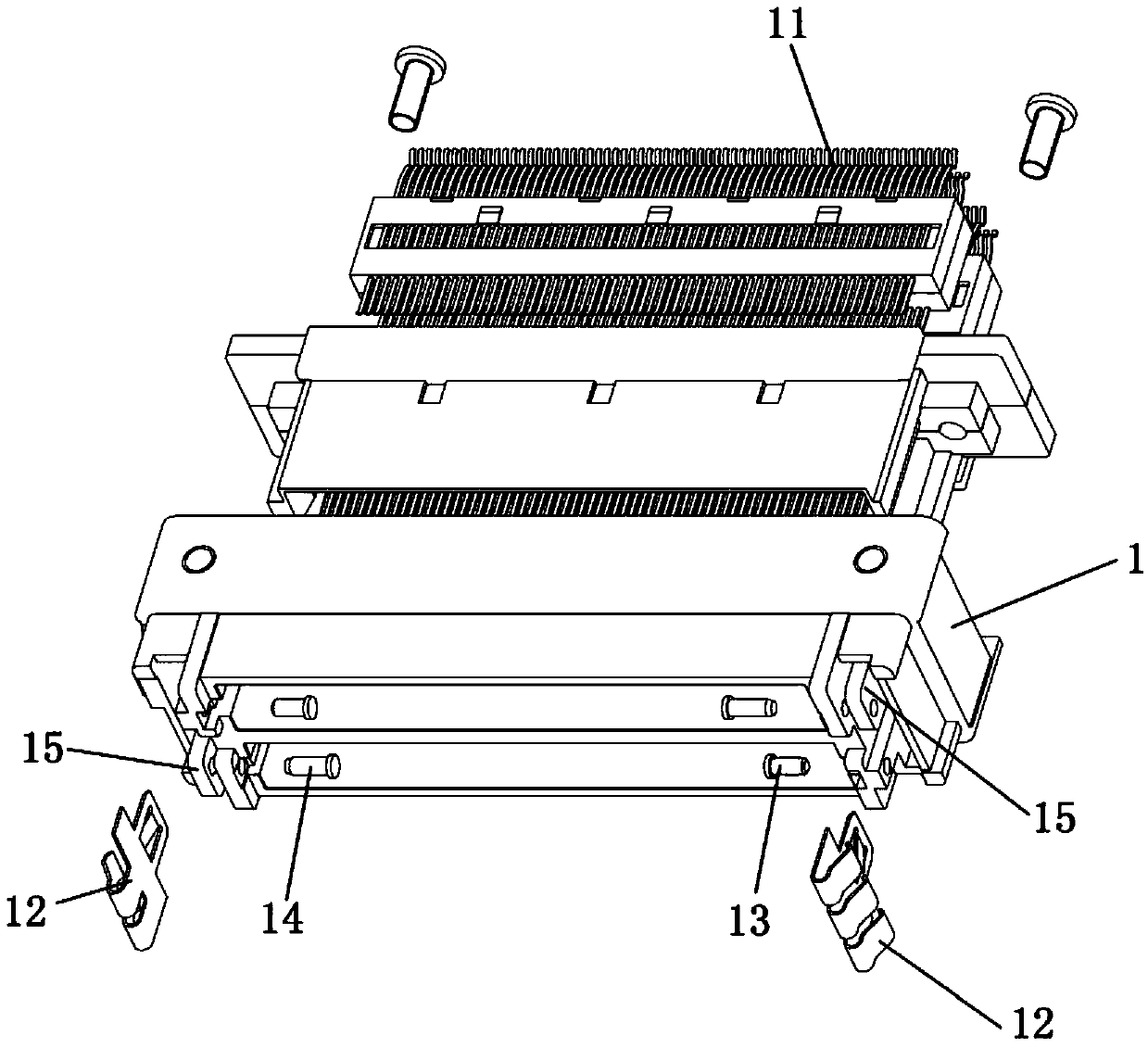
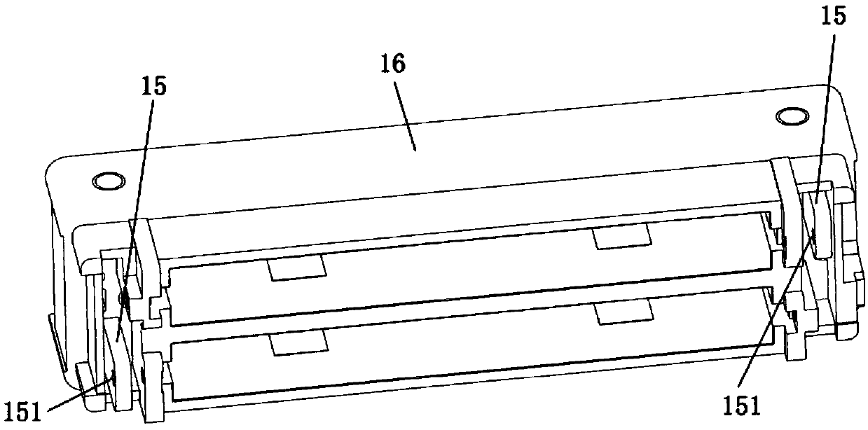
[0042] Such as Figure 1 to Figure 5 As shown, the connector includes a plug 1 and a socket 2 adapted to the plug 1. The plug 1 is provided with plug contacts 11 in groups, and the socket 2 is provided with socket contacts 21, plug contacts 11 and socket contacts in groups. 21 Correspondingly, the same plug contact group and the same socket contact group are arranged in the length direction of the connector, and multiple contact groups are arranged side by side in the width direction of the connector. The contact piece group can be provided with only one group, or can be set as two groups, three groups, four groups, six groups, etc. The specific number is determined by the volume of the transmission circuit and the connector actually required.

[0043] Such as figure 1 and figure 2 As shown, the plug contact 11 is installed in ...


PUM


Abstract

The invention relates to the technical field of connector devices, and in particular relates to a connector and a plug thereof. The connector comprises the plug and a socket. The plug comprises a plugcasing body and a plug contact. A lockpin which matches a latch hook on the matched socket is arranged on the plug casing body. The cantilever end of the lockpin is provided with an anti-slanting insertion identification body. The anti-slanting insertion identification body is located on one end, which is away from the casing body, of the lockpin. During the mating process of the plug and the socket, if a tilt angle which does not meet a set angle requirement is present, the anti-slanting insertion identification body is in direct stop cooperation with the latch hook to restrict the rotationof the latch hook. When an operator rotates a rotation shaft, the rotation shaft is unable to rotate or unable to rotate smoothly. Feedback is directly given to the operator. The operator realizes that the latch hook is unable to rotate and restricted by the anti-slanting insertion identification body, and then adjusts the plugging angle of the plug and socket again. The problem of safety accidents caused by poor or unachievable conduction of a contact pad, which is caused by direct plugging of the plug and the socket, is avoided.

Description

Technical field [0001] The invention relates to the technical field of connector devices, in particular to a connector and a plug thereof. Background technique [0002] With the continuous development of technology, the number of power transmission circuits in the electrical connector is increasing. For the connector that realizes the conductive connection by the contact deformation of the conductive contact pieces in the plug and the socket, the insertion resistance of the plug and the socket during the mutual mating process Also getting bigger. [0003] In order to reduce or eliminate the insertion resistance of the connector during the mating process, technicians have proposed a technical solution of using a booster structure to deform the conductive contacts before mating, so that the insertion force is reduced or even reduced to zero. For example, the application publication number is CN108429033A, and the patent application document with the application publication date of 2...

Claims


Application Information

Patent Timeline
IPC IPC(8): H01R13/641H01R24/00
CPCH01R13/641H01R24/005
Inventor 谷天赐李向辉尚中选张智宇
Owner CHINA AVIATION OPTICAL-ELECTRICAL TECH CO LTD
Why Eureka
Try Eureka