Communication control method, device, system, charging box and wireless earphone

A technology of wireless earphones and control methods, which is applied in the direction of earpieces/earphone accessories, rechargeable batteries/devices, earphone mechanical/electronic switches, etc., which can solve problems such as high cost, poor product stability, and limited communication rate, and reduce material costs. , Reduce development difficulty, improve stability and reliability

Active Publication Date: 2019-12-24
GOERTEK INC
View PDF5 Cites 13 Cited by
  • Summary
  • Abstract
  • Description
  • Claims
  • Application Information

AI Technical Summary

Problems solved by technology

[0003] At present, most of the wireless earphones and charging boxes on the market use 3pin contact connection to realize charging and communication functions. Although some products use 2pin contact connection to realize charging and communication functions, the 2pin contact in the prior art The connection method is often implemented in the following two ways: 1. Realize the communication and charging functions between the charging box and the wireless earphone by adding a dedicated communication chip (such as AMS or Maxim's dedicated chip), but the price of this dedicated chip is high and The communication rate is limited, and there is no market competitiveness in most customer needs and cannot be used; 2. Control the external single-pole double-throw switch through a dedicated CPLD (programmable logic device) or processor (such as a single-chip microcomputer) to achieve control communication Or the transmission of charging status, but because this method is limited by high cost and poor product stability, it cannot meet the needs of customers in the front-end market

Method used


Image

  • Communication control method, device, system, charging box and wireless earphone
  • Communication control method, device, system, charging box and wireless earphone
  • Communication control method, device, system, charging box and wireless earphone

Examples


Embodiment Construction

[0058] In order to make the purpose, technical solutions and advantages of the embodiments of the present invention clearer, the technical solutions in the embodiments of the present invention will be clearly and completely described below in conjunction with the drawings in the embodiments of the present invention. Obviously, the described embodiments It is a part of embodiments of the present invention, but not all embodiments. Based on the embodiments of the present invention, all other embodiments obtained by persons of ordinary skill in the art without making creative efforts belong to the protection scope of the present invention.

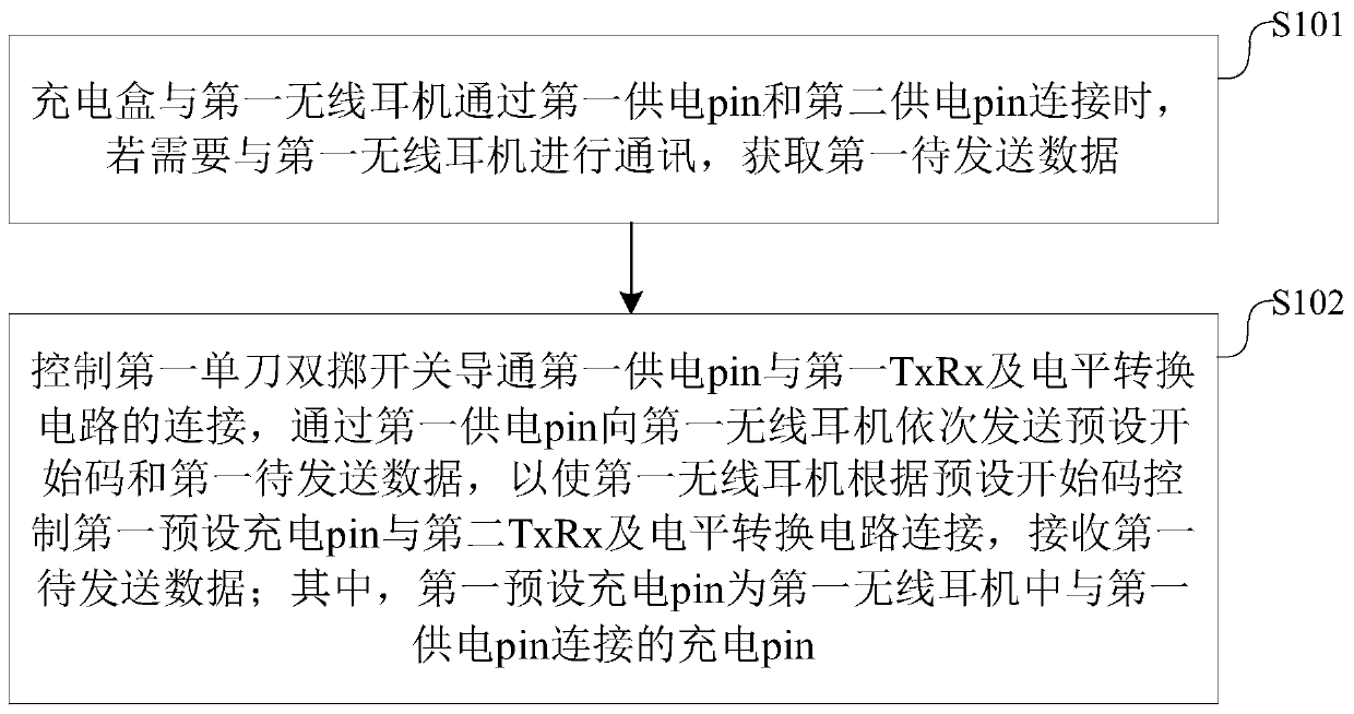
[0059] Please refer to figure 1 , figure 1 It is a flowchart of a communication control method provided by an embodiment of the present invention. The method can include:

[0060] Step 101: When the charging box is connected to the first wireless earphone through the first power supply pin and the second power supply pin, if it is necessar...


PUM


Abstract

The invention discloses a communication control method, a device, a system, a charging box and a wireless earphone, and the method comprises the steps: obtaining first to-be-transmitted data if the charging box needs to communicate with the first wireless earphone when the charging box is connected with the first wireless earphone through a first power supply pin and a second power supply pin; controlling the first single-pole double-throw switch to connect the first power supply pin with the first TxRx and level conversion circuit, and sequentially sending a preset start code and first to-be-sent data to the first wireless earphone through the first power supply pin; according to the method, the preset start code and the first to-be-sent data are sent in sequence; the wireless earphone can be switched between charging and communication, the charging and communication functions between the charging box and the wireless earphone are simply and efficiently realized by utilizing simple circuit construction, the development difficulty of engineers is reduced, an additional communication chip and an additional control device are not needed, and the material cost of the product is reduced.

Description

technical field [0001] The present invention relates to the technical field of portable listening devices, in particular to a communication control method, device, system, charging box and wireless earphone. Background technique [0002] Current earphones can be divided into wired earphones and wireless earphones, wherein wired earphones require two left and right earphones to form left and right sound channels through a wired connection to produce stereo effects, which is very inconvenient to wear. The wireless headset communicates with the terminal through a wireless communication protocol (such as Bluetooth). Compared with wired headsets, it has the characteristics of no need to pack data cables and is easy to use. Among them, the latest true wireless interconnected stereo bluetooth earphone (TWS earphone) is a typical type of wireless earphones. For example, the wireless earphones of TWS earphones often need a matching charging box to charge the wireless earphones, and n...

Claims


Application Information

Patent Timeline
Patent Type & Authority Applications(China)
IPC IPC(8): H04R1/10H04R3/00
CPCH04R1/1041H04R3/00H04R2420/03H04R1/1025H04R1/1016H04R2460/17G06F3/162G06F3/165
Inventor 郎允森
Owner GOERTEK INC
Why Eureka
Try Eureka