Battery charger

A technology for battery chargers and chargers, which is applied to battery circuit devices, current collectors, electric vehicles, etc., and can solve the problems of chargers not having the function of recharging in reverse connection, increasing circuit costs, charging, etc., to reduce the number of components and The effect of PCB board area and circuit cost saving

Inactive Publication Date: 2007-10-17
深圳市芯森纳电子有限公司
0 Cites 7 Cited by

AI-Extracted Technical Summary

Problems solved by technology

[0002] The existing charger market is full of various chargers, some of which do not have the function of reverse charging, that is, the battery cannot be charged when the polarity of the battery is reversed, and the battery needs to be adjusted manually or by other devices. polarity to complete the normal char...

Method used

[0017] As shown in Figure 2C, this figure is a simple schematic diagram of another preferred embodiment of the present invention. Compared with Fig. 2A, this preferred embodiment also uses MOS field effect transistors as controlled sources, that is, both controlled source 1 and controlled source 3 use P-channel MOS transistors, and controlled source 2 and controlled source 4 both use P-channel MOS transistors. N-channel MOS transistors are used, only the gate of the first field effect transistor is coupled to the gate of the second field effect transistor and connected to the node Y through the connection R, and the gate of the third field effect transistor is coupled to the gate of the fourth field effect transistor And connected to the node X through the connection Q, a fifth field effect transistor (150) is added, whi...

Abstract

A battery charger that can automatically identificate the battery polarity, includes a state/polarity identification module (200), a controller (300) and a rechargeable drive unit (100). Wherein the state/polarity identification module (200) automaticlly identificates the unladen, short-circuit, over-current, positive battery connecting, and reverse battery connecting condition of the charger, and detects the state of the battery, so as to generate the corresponding state signal; the controller (300) controls the switching action of the rechargeable drive unit (100) according to the state signal, thus choosing the correct charging circuit and the charge current, and reaching rechargeable function of battery inverse. The circuit is integrated into a chip and greatly reduces the circuit costs.

Application Domain

Technology Topic

Image

  • Battery charger
  • Battery charger
  • Battery charger

Examples

  • Experimental program(1)

Example Embodiment

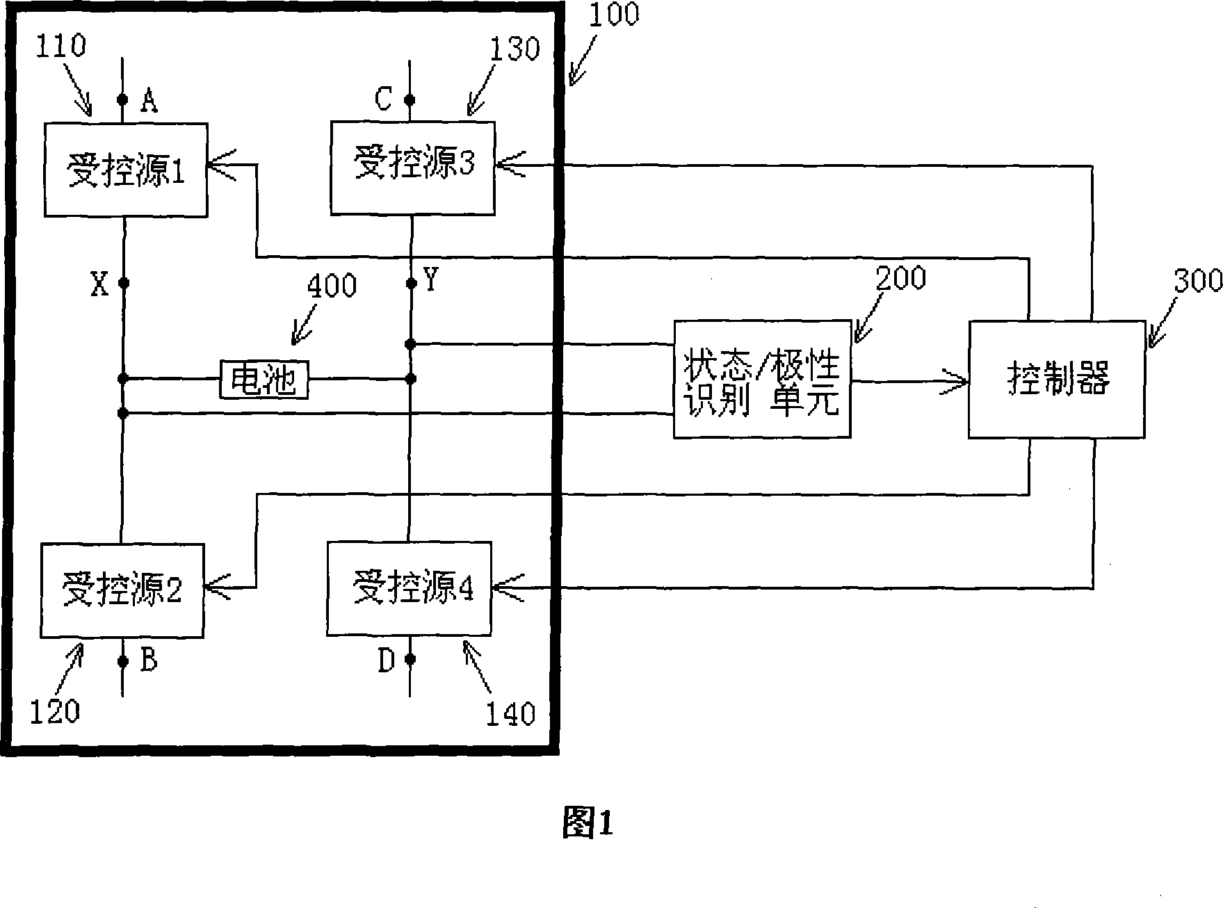
[0014] Most of the known battery chargers need to manually or use other devices to adjust the battery polarity to complete the normal charging function when the battery is reversed. Some chargers have the function of recharging the battery, but they are all built with discrete components. , occupying a large PCB board area, and accurate detection voltage will further increase the circuit cost. In view of this, the present invention proposes a battery charger that can automatically identify the polarity of the battery and can charge the battery in reverse connection.
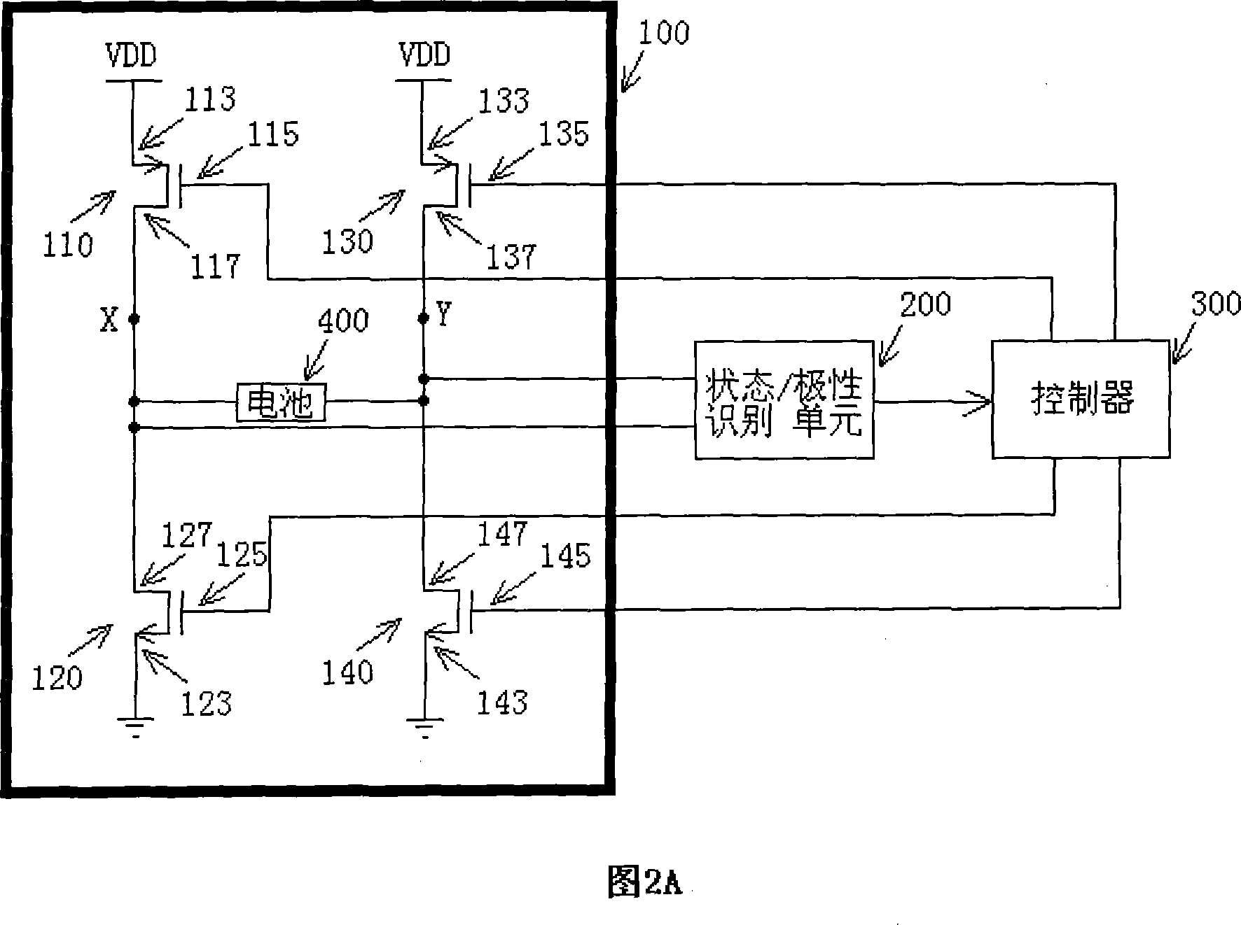
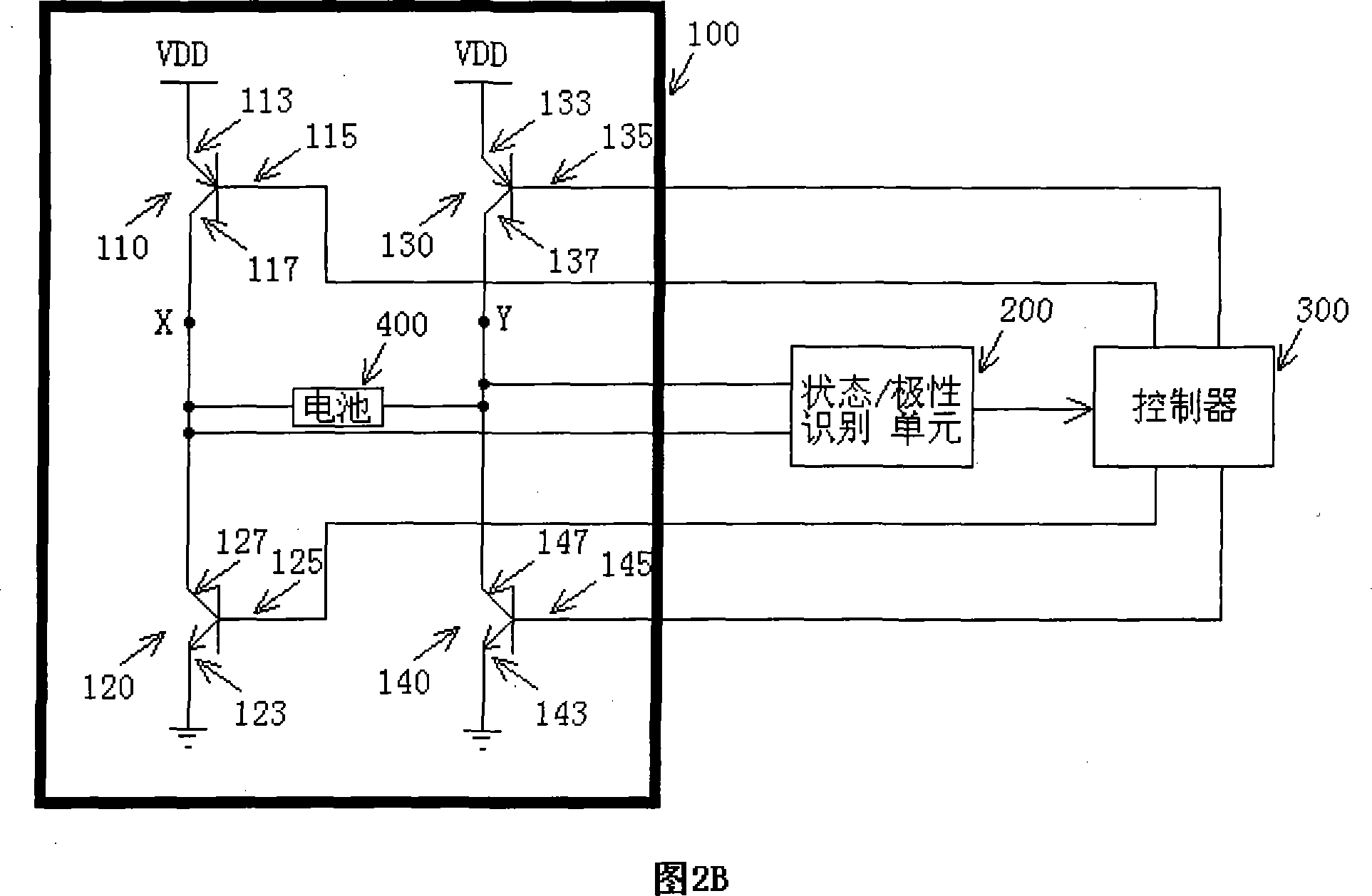
[0015] As shown in Fig. 2A, this figure is a simple schematic diagram of a preferred embodiment of the present invention. In this example, a MOS field effect transistor is used as a controlled source, wherein the first field effect transistor (110) is a P channel MOS transistor, which has a source (113), a drain (117) and a gate (115), wherein The source (113) is connected to the power supply, the drain (117) is connected to the node X, and the gate (115) is connected to the first output of the controller (300); the second field effect transistor (120) is an N-channel MOS transistor, which has Source (123), drain (127) and gate (125), wherein the source (123) is grounded, and the drain (127) is coupled to the drain (117) of the first field effect transistor (110) at node X , the gate (125) is connected to the second output of the controller (300); the third field effect transistor (130) is a P channel MOS transistor, which has a source (133), a drain (137) and a gate (135 ), wherein the source (133) is connected to the power supply, the drain (137) is connected to the node Y, and the gate (135) is connected to the third output of the controller (300); the fourth field effect transistor (140) is an N-channel MOS transistor , which has a source (143), a drain (147) and a gate (145), wherein the source (143) is grounded, and the drain (147) is coupled to the drain (137) of the third field effect transistor at node Y , the gate (145) is connected to the fourth output of the controller (300). In a preferred embodiment of the present invention, the state/polarity identification unit (200) will automatically identify the charger's no-load, short circuit, overcurrent, battery positive connection and battery reverse connection conditions and detect battery voltage status, and generate corresponding status signals to the control The input of the device (300). The charger is connected to the battery and the battery is not saturated: when the battery terminal connected to node X is the positive pole of the battery and the battery terminal connected to node Y is the negative pole of the battery, the first field effect transistor (110) and the fourth field effect transistor (140) are turned on , the second field effect transistor (120) and the third field effect transistor (130) are turned off, at this time the battery charging circuit is: power supply VDD---first field effect transistor (110)---battery positive pole---battery Negative pole---the fourth field effect transistor (140)---ground; The field effect transistor (130) is turned on, and the first field effect transistor (110) and the fourth field effect transistor (140) are turned off. At this time, the battery charging circuit is: power supply VDD --- the third field effect transistor (130) -- -battery positive pole---battery negative pole---second field effect transistor (120)---ground. When the charger is connected to the battery and the battery is saturated: the controller (300) controls the switching action of the four MOS transistors to cut off the battery charging circuit to prevent the battery from being overcharged. In addition, the jumper (Metal Option) in the IC layout can be used to adjust the size of the MOS transistor to obtain the required charging current value.
[0016] As shown in FIG. 2B , this figure is a simple schematic diagram of another preferred embodiment of the present invention. Compared with Figure 2A, this preferred embodiment uses bipolar transistors instead of MOS field effect transistors, that is, both controlled source 1 and controlled source 3 use PNP transistors, and controlled source 2 and controlled source 4 both use NPN transistors , the same circuit function can be accomplished through different process options.
[0017]As shown in FIG. 2C , this figure is a simple schematic diagram of another preferred embodiment of the present invention. Compared with Fig. 2A, this preferred embodiment also uses MOS field effect transistors as controlled sources, that is, both controlled source 1 and controlled source 3 use P-channel MOS transistors, and controlled source 2 and controlled source 4 both use P-channel MOS transistors. N-channel MOS transistors are used, only the gate of the first field effect transistor is coupled to the gate of the second field effect transistor and connected to the node Y through the connection R, and the gate of the third field effect transistor is coupled to the gate of the fourth field effect transistor And connected to the node X through the connection Q, a fifth field effect transistor (150) is added, which is a P channel MOS transistor with a source (153), a drain (155) and a gate (157), Wherein the source (153) is connected to the power supply, and the drain (157) is coupled to the source (113) of the first field effect transistor and the source (133) of the third field effect transistor. From a functional point of view, the fifth field effect transistor, the connection Q and the connection R belong to the state/polarity recognition unit and the controller category, and this embodiment realizes automatic adjustment charging through simple circuit connections such as the connection Q and the connection R The purpose of the loop simplifies the circuit structure.
[0018] The above are only preferred embodiments of the present invention, and other control switching devices and combinations can also be selected as the charging drive unit in the present invention, which will not be listed here.
[0019] As before, the battery charger that can automatically identify the battery polarity of the present invention has the advantages of:
[0020] 1. It can automatically identify the polarity of the battery and realize the function of recharging the battery in reverse connection;
[0021] 2. The circuit is integrated into the chip, which greatly reduces the number of components and PCB board area, and saves the cost of the circuit.
[0022] In summary, the preferred embodiments of the present invention are as described above, but they are not intended to limit the scope of the present invention. The protection scope of the present invention should be based on the claims. The present invention can be made by those of ordinary skill in the art. Modifications and modifications, but still belong to the creative spirit of the present invention and the scope defined by the appended claims.

PUM

no PUM

Description & Claims & Application Information

We can also present the details of the Description, Claims and Application information to help users get a comprehensive understanding of the technical details of the patent, such as background art, summary of invention, brief description of drawings, description of embodiments, and other original content. On the other hand, users can also determine the specific scope of protection of the technology through the list of claims; as well as understand the changes in the life cycle of the technology with the presentation of the patent timeline. Login to view more.

Similar technology patents

Classification and recommendation of technical efficacy words

Why Eureka
Try Eureka