Vehicle door electric pedal and vehicle

A technology of electric pedals and car doors, which is applied to the arrangement, transportation and packaging of vehicle components, pedals or ladders, and can solve the problem that the left and right pedals cannot be retracted and stored.

Active Publication Date: 2019-12-27
长春众鼎科技有限公司
View PDF4 Cites 1 Cited by
  • Summary
  • Abstract
  • Description
  • Claims
  • Application Information

AI Technical Summary

Problems solved by technology

[0004] In order to solve the technical problem that the left and right pedals of the existing car door pedals cannot be retracted and retracted, the invention provides an electric door pedal

Method used


Image

  • Vehicle door electric pedal and vehicle
  • Vehicle door electric pedal and vehicle
  • Vehicle door electric pedal and vehicle

Examples


Embodiment 1

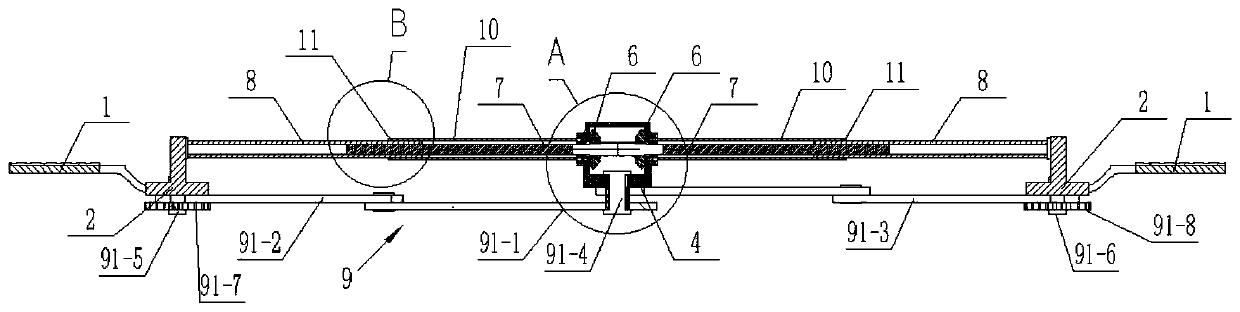
[0043] Embodiment one: see Figure 1-9 , an electric door pedal, which includes two pedals 1, a motor 3, a transmission box 4, a driving bevel gear 5, two driven bevel gears 6, two screw rods 7, two screw rod sleeves 8 and a two-way telescopic frame 9.

[0044] The two pedals 1 are arranged symmetrically at intervals from left to right, and the transmission box 4 is located in the middle between the two pedals 1 .

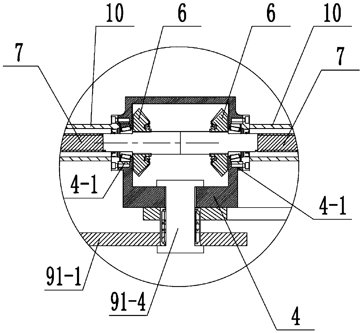
[0045] The driving bevel gear 5 and two driven bevel gears 6 are rotatably installed in the transmission box 4, the two driven bevel gears 6 are coaxially arranged and symmetrically distributed, and the driving bevel gear 5 is simultaneously connected with the two driven bevel gears. Driven bevel gear 6 meshing connection.

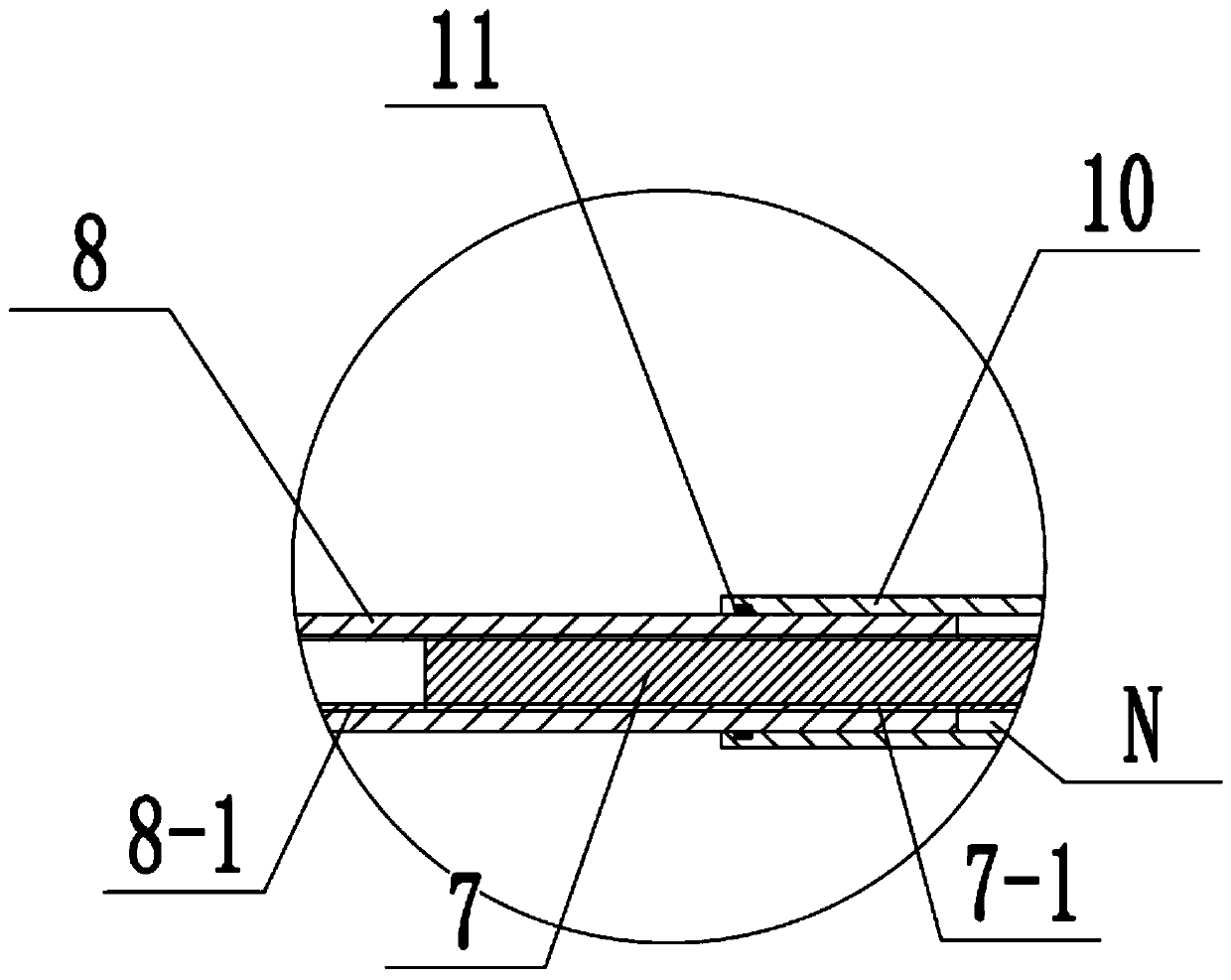
[0046] The two screw rods 7 are coaxially fixed to the two driven bevel gears 6 respectively.

[0047] See Figure 8-9 Specifically, two first shaft holes 4-1 are respectively provided on the left and right side walls of the transmission bo...

Embodiment 2

[0072] Embodiment 2: This embodiment is basically the same as Embodiment 1, except that the specific structure of the two-way telescopic frame 9 is different.

[0073] In this example: see Figure 10 , the two-way telescopic frame 9 includes two intermediate parallel rods 92-1, two first parallel connecting rods 92-2 and two second parallel connecting rods 92-3; the two intermediate parallel rods 92-1 are parallel The middle parts of the two middle parallel rods 92-1 are rotatably mounted on the transmission box 4; the two first parallel connecting rods 92-2 are parallel to each other and the two first parallel connecting rods 92-2 One end is respectively hinged with one end of the two middle parallel rods 92-1, and the other ends of the two first parallel connecting rods 92-2 are rotatably mounted on one of the pedal connecting seats 2; The connecting rods 92-3 are parallel to each other and one end of the two second parallel connecting rods 92-3 is respectively hinged to th...

Embodiment 3

[0077] Embodiment 3: This embodiment is basically the same as the above-mentioned other embodiments, except that the specific structure of the two-way telescopic frame 9 is different.

[0078] In this example: see Figure 11 , the two-way telescopic frame 9 includes two cross arms 93-1, two first four-bar linkages 93-2 and two second four-bar linkages 93-3; the two cross arms 93- 1 Cross distribution and the middle parts of the two cross arm rods 93-1 are installed on the transmission box 4 through the third hinge shaft 93-4; The mechanism 93-2 is connected to one of the pedals 1; the other ends of the two cross-arms 93-1 are respectively connected to the other pedal 1 through two second four-bar linkage mechanisms 93-3.

[0079] Specifically, one end of the two cross-arms 93-1 is respectively hinged to the middle part of the inner link of the first four-bar linkage 93-2, and the outer links of the two first four-bar linkage 93-2 are fixed therein. One of the two side ends o...


PUM


Abstract

The invention discloses a vehicle door electric pedal which is characterized by comprising two pedals, a motor, a transmission case, a driving bevel gear, two driven bevel gears, two screw rods, two screw rod sleeves and a bidirectional telescopic frame, wherein the transmission case is positioned between the two pedals, the driving bevel gear and the two driven bevel gears are rotatably mounted in the transmission case, and the two driven bevel gears are coaxially arranged; the driving bevel gear is connected with the two driven bevel gears in a meshed manner at the same time, the two lead screws are coaxially and fixedly connected with the two driven bevel gears respectively, and the two lead screw sleeves are in threaded fit with the two lead screws respectively; the two lead screws areidentical in rotation, and the outer side ends of the two lead screw sleeves are fixedly connected with the two pedals respectively; the motor is connected with the driving bevel gear, and the transmission box is separately connected with the two pedals through the bidirectional telescopic frame. Different from an existing structural design, according to the present invention, the single motor isadopted for driving, and the two pedals can automatically extend outwards or retract and can be stored at the same time.

Description

technical field [0001] The invention relates to an electric pedal for a car door and a vehicle. Background technique [0002] The door pedals are mainly installed on models with high chassis such as commercial vehicles, off-road vehicles, SUVs, pickups, etc., and provide transitional pedaling for passengers to go up and down the left and right doors, making it more convenient for passengers with short legs, the elderly, women and children to ride. [0003] The left and right pedals of the existing door pedals are fixedly arranged under the doors on both sides of the car, and after the left and right doors are closed, the left and right pedals cannot be retracted and protrude outwards, which affects the appearance of the whole vehicle and is more attractive. The passability of driving in the width direction has a certain impact. Contents of the invention [0004] In order to solve the technical problem that the left and right pedals of the existing car door pedals cannot b...

Claims


Application Information

Patent Timeline
Patent Type & Authority Applications(China)
IPC IPC(8): B60R3/02
CPCB60R3/02
Inventor 尹诚郭晓强唐德亮马溶
Owner 长春众鼎科技有限公司
Why Eureka
Try Eureka