Traction wheel with displacement deviation capable of being reduced

A technology of displacement deviation and traction wheel, which is applied in the direction of elevators, transportation and packaging in buildings, can solve the problems of horizontal wire deviation, high equipment cost, and easy to cause deviation, etc., and achieves easy positioning, simple steps, and easy to use The effect of less equipment

Active Publication Date: 2019-12-27
浙江尼邦电梯有限公司
View PDF10 Cites 0 Cited by
  • Summary
  • Abstract
  • Description
  • Claims
  • Application Information

AI Technical Summary

Problems solved by technology

[0002] When the traction sheave is installed, the installation displacement needs to be corrected. The correcting steps are: fix a horizontal iron wire above the traction machine, hang two vertical lines from this horizontal iron wire to align with the car frame on the wooden floor Then calculate the pitch circle diameter of the traction sheave according to the center of the traction rope, then hang another plumb line at the corresponding position on the horizontal iron wire, and finally use these standard lines to install the guide wheel Correcting the position, the steps are relatively complicated, and two people are required to coordinate the positioning of the standard line, and in the process of using the vertical line, the horizontal iron wire is easy to shift due to the gravity of the vertical line and cannot be detected. At the same time, although this method can be used to determine The left and right position of the traction wheel relative to the guide wheel, but because the horizontal iron wire is fixed above the traction machine, there is a certain vertical distance from the traction wheel, so the front and rear positions of the guide wheel and the traction wheel can only be determined visually, which is easy Cause deviation, or use other tools to assist, and the cost of equipment is high

Method used


Image

  • Traction wheel with displacement deviation capable of being reduced
  • Traction wheel with displacement deviation capable of being reduced
  • Traction wheel with displacement deviation capable of being reduced

Examples


Embodiment Construction

[0024] The following are specific embodiments of the present invention and in conjunction with the accompanying drawings, the technical solutions of the present invention are further described, but the present invention is not limited to these embodiments.

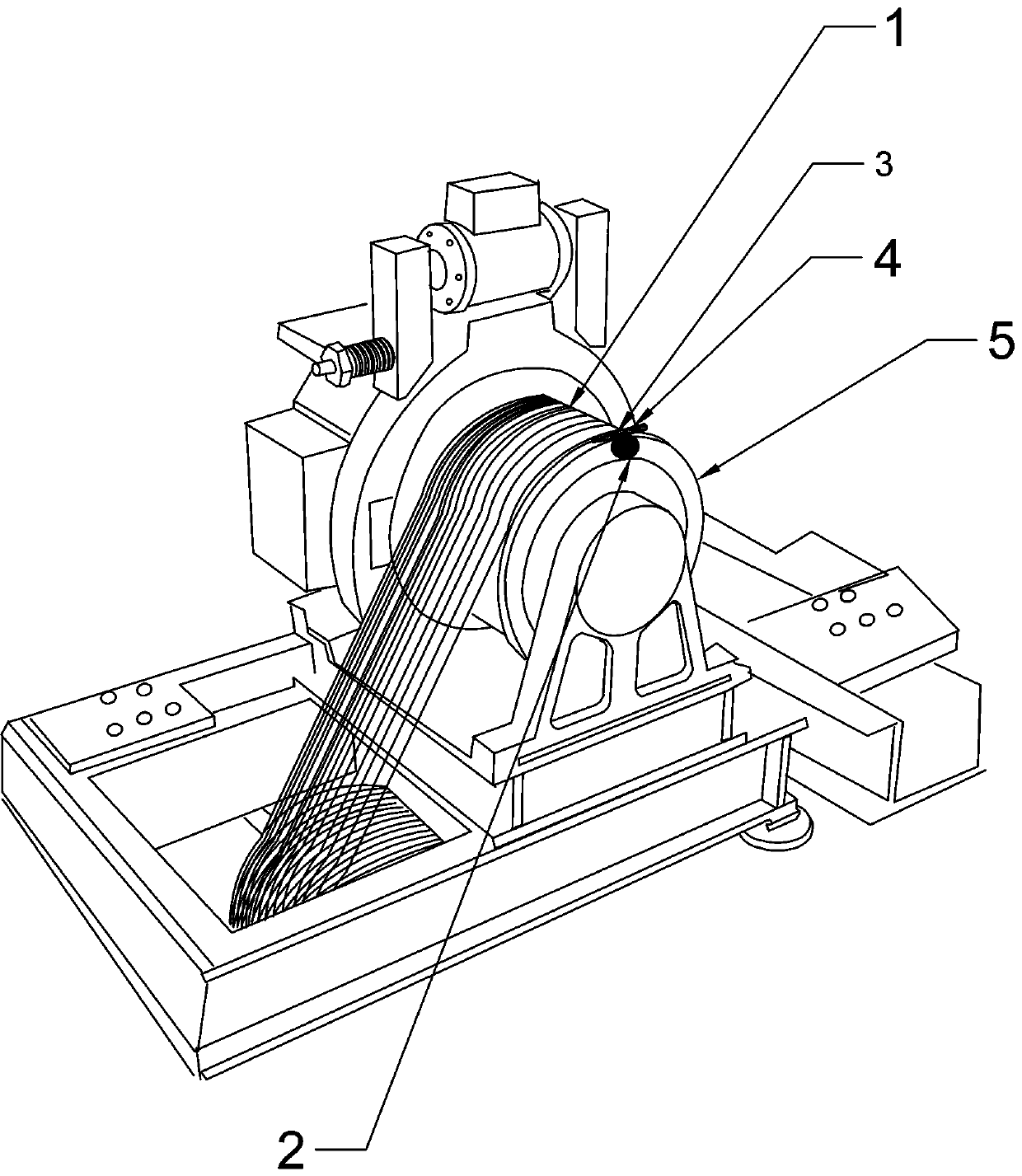
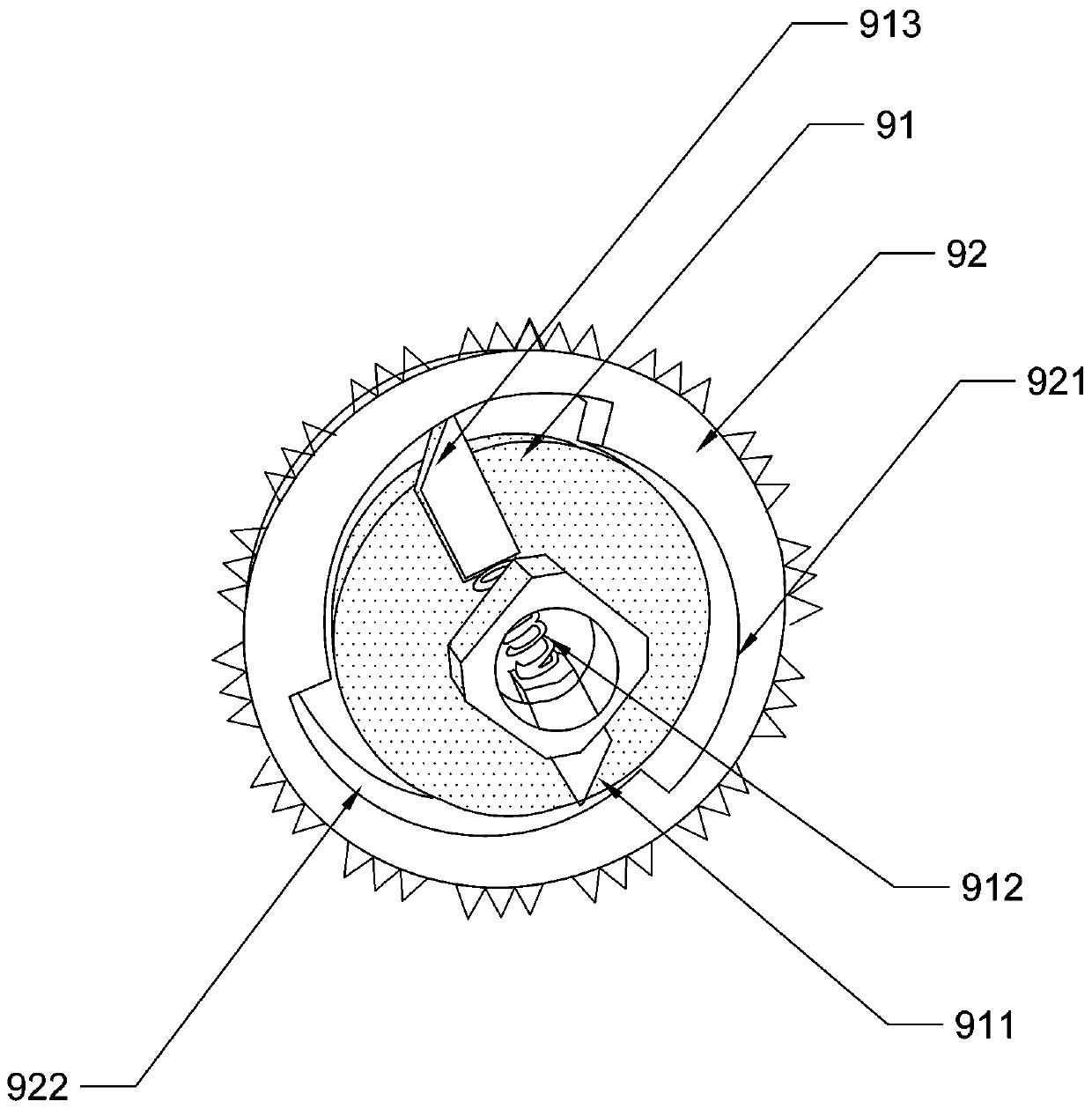
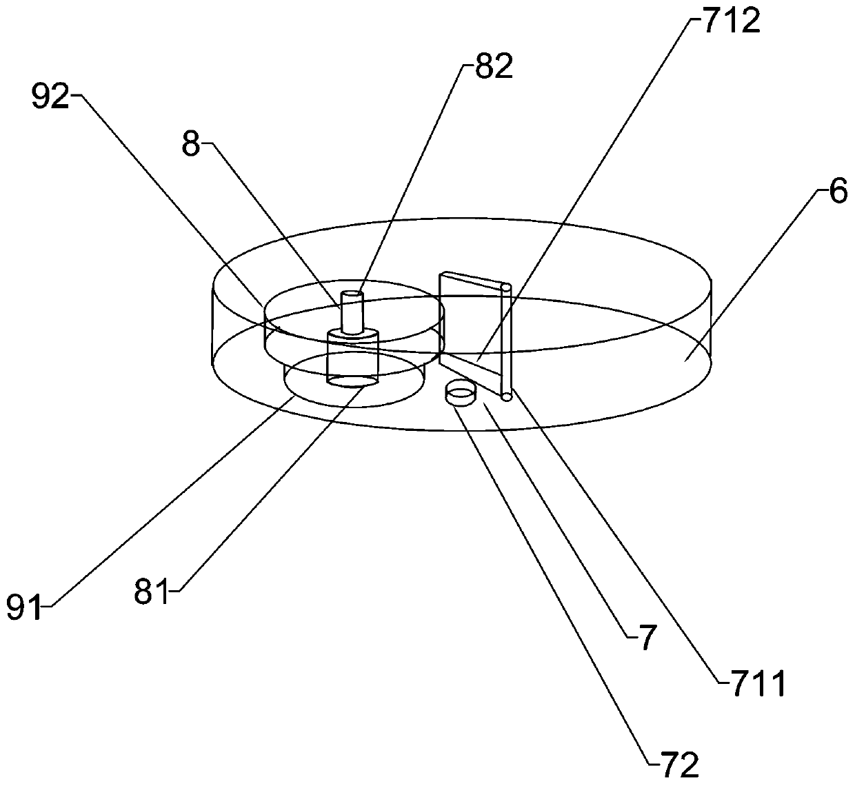
[0025] The present invention provides a traction sheave that reduces the displacement deviation of the traction sheave, such as figure 1 , figure 2 As shown, it includes a wheel body, a wiring device tangent to the wheel body, a laser pointer that is tangent to the wiring device and the wheel body at the same time, and the laser pointer is fixed with a mini level, such as image 3 As shown, the wiring device includes a casing, a chassis fixed to the traction wheel and a locking block, a reel for winding up the lead wire, a toothed disc sleeved on the reel, and the toothed disc is connected to the The reel is coaxial and rotates synchronously. The locking block includes a knob and a limiter. The knob is provided with a po...


PUM


Abstract

The invention provides a traction wheel with the displacement deviation capable of being reduced. The traction wheel comprises a wheel body, a wiring device and a laser pen. The wiring device is tangent to wheel body. The laser pen is simultaneously tangent to the wiring device and the wheel body and is fixedly provided with a mini level. The wiring device comprises a housing, a chassis, a lockingblock, a winding drum and a toothed disc. The chassis and the locking block are fixedly arranged on the traction wheel. The winding drum is used for winding a lead wire. The toothed disc sleeves thewinding drum. The toothed disc and the drum are coaxial and rotate synchronously. The locking block comprises a knob and a limiting part. The knob is provided with a positioning rod and a locking partpenetrating through the positioning rod. The locking part is provided with a toothed part which meshes with the toothed disc. When the knob is rotated to enable the toothed disc to mesh with the locking part, the locking part is stopped by the limiting part, a guide wheel is precisely positioned, the displacement deviation of the traction wheel is reduced, positions can be simply determined, operation is facilitated, and less equipment is used.

Description

technical field [0001] The invention relates to the field of traction elevators, in particular to a traction sheave that reduces the displacement deviation of the traction sheave. Background technique [0002] When the traction sheave is installed, the installation displacement needs to be corrected. The correcting steps are: fix a horizontal iron wire above the traction machine, hang two vertical lines from this horizontal iron wire to align with the car frame on the wooden floor Then calculate the pitch circle diameter of the traction sheave according to the center of the traction rope, then hang another plumb line at the corresponding position on the horizontal iron wire, and finally use these standard lines to install the guide wheel Correcting the position, the steps are relatively complicated, and two people are required to coordinate the positioning of the standard line, and in the process of using the vertical line, the horizontal iron wire is easy to shift due to th...

Claims


Application Information

Patent Timeline
IPC IPC(8): B66B11/06
CPCB66B11/0075
Inventor 金卫琴尤惠星郑燕平
Owner 浙江尼邦电梯有限公司
Why Eureka
Try Eureka