Force-increasing demolding device for large-diameter vertical shaft template

A demoulding device and large-diameter technology, which can be used in shaft equipment, shaft lining, mining equipment, etc., can solve the problems of increased reaction force of elastic deformation of adhesive formwork, large contact area between formwork and concrete, and increased equipment requirements. , to achieve the effect of reducing overturning force, solving the difficulty of demoulding, and saving economic costs

Active Publication Date: 2019-12-27
SHANGHAI FOUND ENG GRP
View PDF5 Cites 0 Cited by
  • Summary
  • Abstract
  • Description
  • Claims
  • Application Information

AI Technical Summary

Problems solved by technology

When pouring the lining wall of a large-diameter and ultra-deep shaft, the formwork used will have higher requirements for diameter, strength, and rigidity. The area in contact with the concrete is relatively large, so the adhesive force that needs to be overcome during demoulding and the reaction force of the elastic deformation of the formwork are greatly increased, resulting in higher requirements for traditional mechanical and hydraulic demoulding equipment
In the same way, this leads to insufficient demoulding force in the self-weight demoulding method or the need to use a huge structure to provide sufficient gravity, which wastes materials and is not economically applicable

Method used


Image

  • Force-increasing demolding device for large-diameter vertical shaft template
  • Force-increasing demolding device for large-diameter vertical shaft template
  • Force-increasing demolding device for large-diameter vertical shaft template

Examples


Embodiment Construction

[0022] A further detailed description will be given below of a large-diameter shaft formwork booster demoulding device of the present invention. In order to make the purpose and features of the present invention more comprehensible, the specific implementation manners of the present invention will be further described below in conjunction with the accompanying drawings.

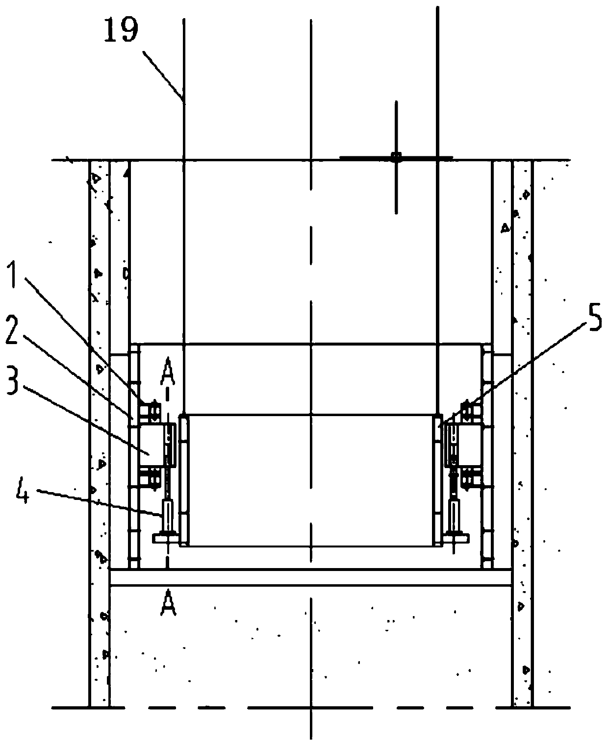
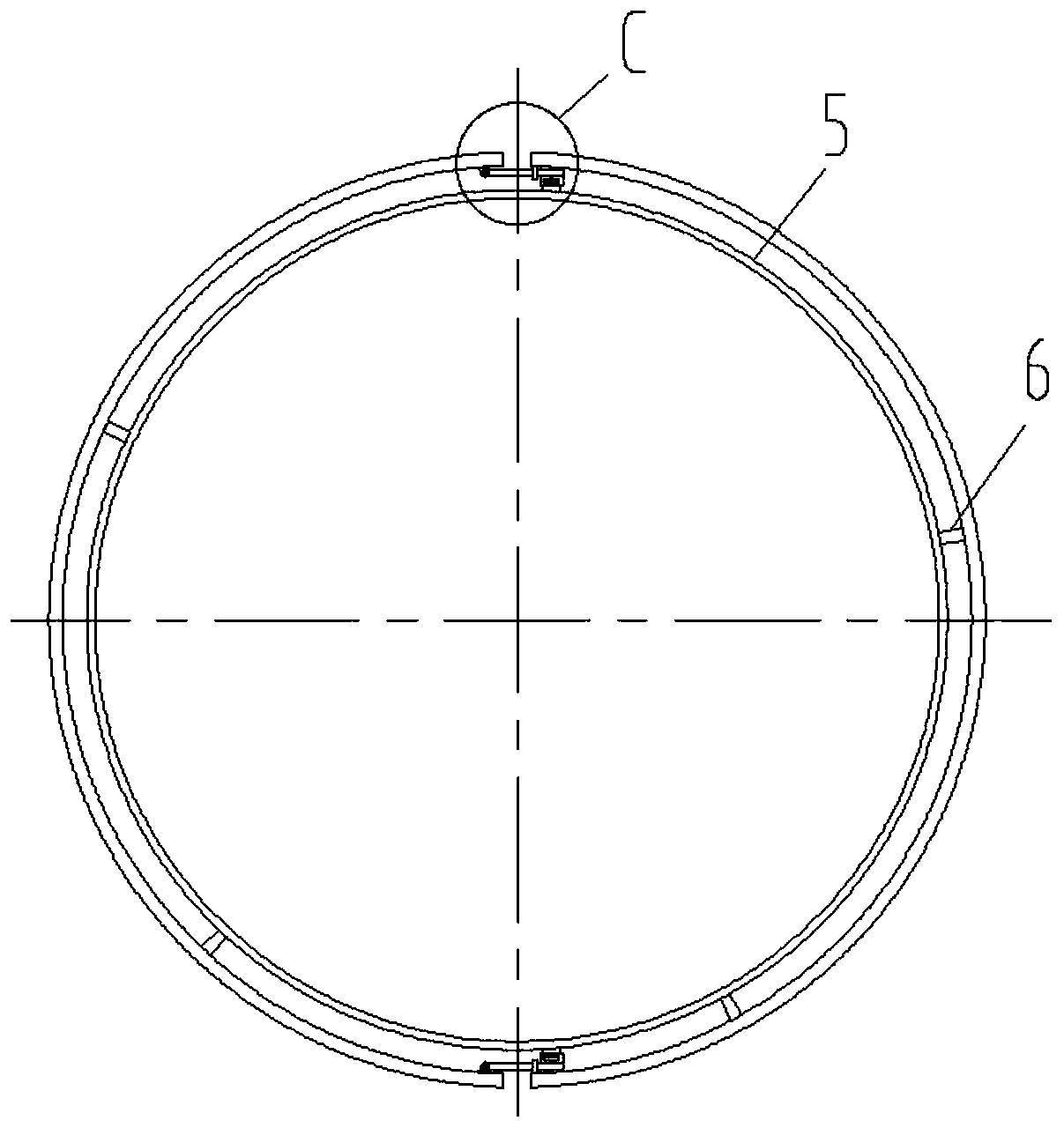
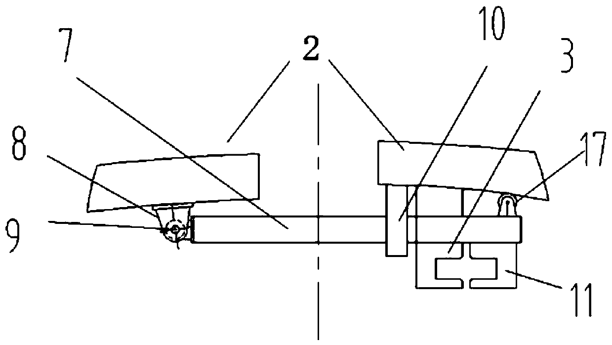
[0023] Such as Figure 1 to Figure 8 As shown, a large-diameter shaft formwork booster demoulding device includes: a hanger 5, a wedge-shaped jack 4, and a pull mechanism. The upper end of the hanger 5 is connected with the lifting wire rope 19, and the hanger 5 hangs the template 2 through the boom 6; the wedge-shaped jack 4 includes: a jack 12, a wedge-shaped head 13, and the jack 12 can be a hydraulic or mechanical jack, and the front and rear sides of the wedge-shaped head 13 are Vertical surface, the left and right sides are inclined planes, have threaded holes on the wedge-shaped head 13, see Figure ...


PUM


Abstract

The invention relates to a force-increasing demolding device for a large-diameter vertical shaft template. A hanger suspends the template through a hanging arm; the jack seat of the wedge-shaped headjack is installed on the outer side of the hanger; a pulling mechanism is composed of a limiting guide door, a fixed inclined groove block and a inclined groove block pulling frame; the fixed inclinedgroove block is welded on the template; a inclined groove is formed on one side of the inclined groove block opposite to the inclined groove block pulling frame; the inclined groove block pulling frame is installed on the other side, opposite to one side of the template of the demolding opening where the fixed inclined groove block is located, of the template through a hinge seat; and after passing through the limiting guide door, a double-bevel wedge-shaped hole for the wedge head of the wedge-shaped head jack to move is formed with the fixed inclined groove block, the wedge-shaped head jackmoves in coordination with the double-bevel wedge-shaped hole by pushing the wedge head, so that the wedge-shaped groove formed by the cooperation of the inclined groove block pulling frame and the fixed inclined groove block is enlarged, and the fixed inclined groove block and the inclined groove block pulling frame move in opposite directions, so that the templates on both sides of the templatedemoulding opening are pulled oppositely, and the vertical pushing force is converted into horizontal pulling force, and demoulding is realized.

Description

technical field [0001] The invention relates to a demoulding device for underground construction, in particular to a force-increasing demoulding device for demoulding a pouring formwork for lining a large-diameter shaft. Background technique [0002] In the excavation of underground engineering, the enclosure structure often adopts the form of support or underground diaphragm wall. Taking the shaft as an example, in the soft soil layer, a circle of underground diaphragm wall is built around the excavation area in advance, and then the shaft is excavated, which can greatly Ensure the safety of construction and prevent soil collapse. Generally, after the construction of the underground diaphragm wall, the wall surface is extremely rough and will form an uneven wall surface. At this time, another lining wall of reinforced concrete wall structure will be poured in the diaphragm wall. When pouring the lining wall of a large-diameter and ultra-deep shaft, the formwork used will h...

Claims


Application Information

Patent Timeline
Patent Type & Authority Applications(China)
IPC IPC(8): E21D5/12E21D5/04
CPCE21D5/04E21D5/12
Inventor 李远青龚妍范斌朱德勇顾蓓瑛
Owner SHANGHAI FOUND ENG GRP
Why Eureka
Try Eureka