Range hood
A technology for range hoods and filters, which is applied in the field of range hoods and can solve problems such as limiting the application space of cyclone filters and single range hood solutions
- Summary
- Abstract
- Description
- Claims
- Application Information
AI Technical Summary
Problems solved by technology
Method used
Image


Examples
Embodiment 1
[0030] A range hood embodiment proposed by the present application, such as Figure 4 As shown, the range hood is a top-suction range hood, which includes a cyclone filter, a support 5 , a smoke collection hood 6 , a fan and a casing 7 . The casing 7 is fixedly arranged above the smoke collecting hood 6 , and the fan is arranged in the casing 7 . The number of cyclone filters is two, and the structures of the two cyclone filters are the same. The two cyclone filters are plate-shaped, such as Figures 1 to 3 shown. The number of support members 5 is one. The support member 5 is placed on the range hood, specifically, the fume collecting hood 6 is provided with an air inlet, the support member 5 is placed on the edge of the air inlet, and the air inlet is spaced to form a left inlet and a right opening . Because it is set up, the user can easily remove the support 5 by lifting the support 5 upwards and adjusting a certain angle. The supporting member 5 placed on the range ...
Embodiment 2
[0039] The present application also proposes another embodiment 2 of the range hood, which is further improved on the basis of the above embodiment 1 of the range hood. The main differences between the second embodiment of the range hood and the first embodiment of the range hood are as follows.
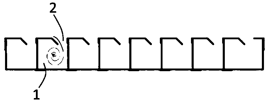
[0040] The air inlets 2 of the two cyclone filters of this range hood embodiment 2 are also all set towards the outside of the range hood, as Figure 5 shown. One ends of the air intake pipes 1 of the two cyclone filters extend toward the same area, forming a recessed structure, which is recessed toward the inside of the range hood, so that the recessed structure forms a smoke cavity. Specifically, one end of the air inlet pipe 1 of the left cyclone filter and one end of the air inlet pipe 1 of the right cyclone filter all extend toward the same area, that is, one end of the air inlet pipe 1 of the left cyclone filter One end of the air intake pipe 1 and the right side cyclone filt...
Embodiment 3
[0043] The present application also proposes another embodiment 3 of the range hood, which is further improved on the basis of the above embodiment 1 of the range hood. The main differences between the third embodiment of the range hood and the first embodiment of the range hood are as follows.
[0044] Embodiment 3 of this range hood is a side suction type range hood, as Image 6 As shown, the smoke collecting hood 6 of the side suction range hood is provided with an inclined airflow inlet. The support member 5 is placed approximately obliquely (the inclination angle of the support member 5 is approximately the same as that of the air inlet), one end of the support member 5 extends upward, and the other end of the support member 5 extends downward, as Image 6 shown. In the third embodiment of the range hood, one end of the air intake duct 1 of the left cyclone filter and one end of the air intake duct 1 of the right cyclone filter both extend toward the support 5 placed ob...
PUM
 Abstract
Description
Claims
Application Information
 - R&D
- Intellectual Property
- Life Sciences
- Materials
- Tech Scout
- Unparalleled Data Quality
- Higher Quality Content
- 60% Fewer Hallucinations
Browse by: Latest US Patents, China's latest patents, Technical Efficacy Thesaurus, Application Domain, Technology Topic, Popular Technical Reports.
© 2025 PatSnap. All rights reserved.Legal|Privacy policy|Modern Slavery Act Transparency Statement|Sitemap|About US| Contact US: help@patsnap.com