A System Calibration Method of Antenna Phase Center of Precision Ranging System

A precision distance measurement and system calibration technology, which is applied in radio wave measurement systems, radio wave reflection/reradiation, and measurement devices, can solve problems such as unguaranteed accuracy, equation distortion errors, and reduced measurement accuracy, so as to reduce signal Propagation link, improve phase test accuracy, and reduce the effect of solving complexity

Active Publication Date: 2021-12-07
XIAN INSTITUE OF SPACE RADIO TECH
View PDF11 Cites 1 Cited by
  • Summary
  • Abstract
  • Description
  • Claims
  • Application Information

AI Technical Summary

Problems solved by technology

This method has better universality, but because it is separated from the precision measurement system, it introduces more noise and environmental interference from external measuring instruments, which reduces the measurement accuracy
[0006] 2. The phase pattern fitting method is used in the specific solution process of the phase center position. This method is related to the order of fitting. If the order is low, the accuracy cannot be guaranteed, and if the order is too high, it will cause the equation to be distorted and generate errors. , so choosing an appropriate fitting equation is critical, and it has relatively large limitations in use.
In addition, the least squares fitting method used in the advanced method can only reduce the random error of measurement, but cannot improve the measurement accuracy, that is, reduce the systematic error
[0007] 3. In the process of solving the phase center, the emission characteristics of the antenna phase center are not considered as a whole, and the scanning range of the design pattern is not targeted, so there is a systematic deviation in the calculation accuracy of the phase center within the required measurement beam range

Method used


Image

  • A System Calibration Method of Antenna Phase Center of Precision Ranging System
  • A System Calibration Method of Antenna Phase Center of Precision Ranging System
  • A System Calibration Method of Antenna Phase Center of Precision Ranging System

Examples


Embodiment Construction

[0092] Below in conjunction with accompanying drawing and specific embodiment the present invention is described in further detail:

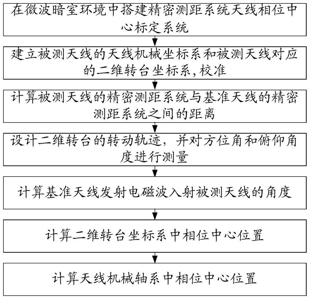
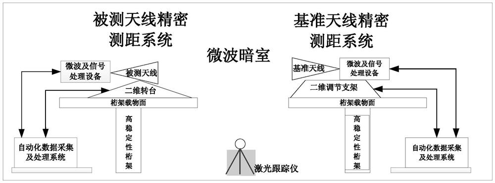
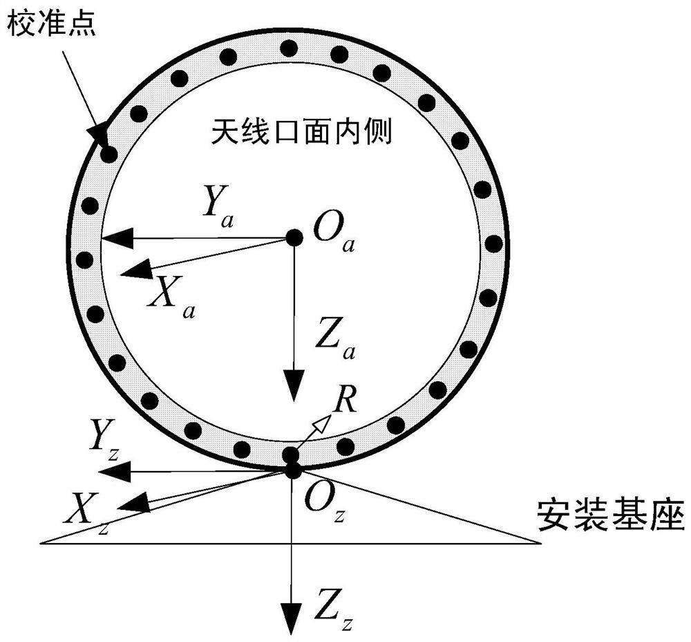
[0093] The invention provides a method for calibrating the phase center of an antenna of a precision ranging system, and provides in detail the configuration of the system where the antenna is located, a calibration test system, a test data processing flow and a specific algorithm. The present invention can obtain the high-precision three-dimensional point coordinates of the phase center at one time through the joint calculation of the ranging value of the system and the angle value output by the turntable within the range of the concerned angle, avoiding the fitting error of the phase pattern in the traditional method, The error of external auxiliary instruments is reduced, and the test accuracy is greatly improved. At the same time, the calibration method has a high degree of automation, less auxiliary instruments outside the system, high test ...


PUM


Abstract

A system calibration method for the antenna phase center of a precision ranging system, which relates to the field of microwave measurement technology; including step 1, setting up a precision ranging system antenna phase center calibration system in a microwave darkroom environment; step 2, establishing the antenna mechanism of the antenna under test Coordinate system and the two-dimensional turntable coordinate system corresponding to the antenna under test; calibration; step three, calculating the distance D between the precision ranging system of the antenna under test and the precision ranging system of the reference antenna; step four, designing the two-dimensional turntable Rotate the trajectory, and measure the azimuth and pitch angle; step five, calculate the angle of the electromagnetic wave emitted by the reference antenna incident on the antenna under test; step six, calculate the phase center position in the two-dimensional turntable coordinate system; step seven, calculate the mechanical axis of the antenna The center position of the middle phase; the present invention reduces the error of external auxiliary instruments and greatly improves the test accuracy. At the same time, the calibration method has a high degree of automation, less auxiliary instruments outside the system, high test accuracy, and a simple and reliable method.

Description

technical field [0001] The invention relates to the technical field of microwave measurement, in particular to a system calibration method for an antenna phase center of a precision ranging system. Background technique [0002] In the high-precision radio measurement system represented by the gravimetric satellite micron-level precision ranging system (KBR) and GNSS receiver, the antenna is the reference point for signal reception, transmission and measurement value output. If the phase center of the antenna changes during the measurement period of interest, errors will be introduced in the output ranging value. Accurately knowing the position of the antenna phase center is very important for online and offline calibration of ranging values, ranging accuracy evaluation, and optimal configuration of ranging systems. [0003] The existing typical antenna phase center calibration methods can be divided into two categories: one is based on microwave anechoic chamber and turntab...

Claims


Application Information

Patent Timeline
Patent Type & Authority Patents(China)
IPC IPC(8): G01S7/40G01S13/08G01S11/02
CPCG01S7/4026G01S11/02G01S13/08
Inventor 刘玄王登峰焦仲科钟兴旺张乔杉杨姗姗任帅蔡晨曦
Owner XIAN INSTITUE OF SPACE RADIO TECH
Why Eureka
Try Eureka