Deicing device for power transmission line

A technology for transmission lines and output terminals, applied in the installation of cables, electrical components, overhead installation, etc., can solve the problems of difficulty in removing ice cubes, falling transmission lines, and small adaptability, achieving good deicing effect and small space occupation. , the effect of convenient operation

Pending Publication Date: 2019-12-27
国网河南省电力公司新安县供电公司 +1
View PDF0 Cites 2 Cited by
  • Summary
  • Abstract
  • Description
  • Claims
  • Application Information

AI Technical Summary

Problems solved by technology

[0002] The icing disaster of transmission lines is one of the main factors that affect the safety of transmission lines in winter. The tower collapsed, causing the transmission line to be paralyzed
[0003] Most of the deicing methods currently used are rigid deicing. The ice on the surface of the transmission line is removed by deicing thorns or deicing shovels. This deicing method is easy to cause damage to the transmission line, and improper operation is easy to pull the transmission line. Cause the power line to fall, and it is difficult to remove the ice between the power lines, because some power lines will sink under the pressure of the ice, the commonly used deicing device lacks a height adjustment device, and the scope of application is small

Method used


Image

  • Deicing device for power transmission line
  • Deicing device for power transmission line
  • Deicing device for power transmission line

Examples


Embodiment Construction

[0016] The technical solutions in the embodiments of the present invention will be clearly and completely described below in conjunction with the accompanying drawings in the embodiments of the present invention. Obviously, the described embodiments are only some of the embodiments of the present invention, not all of them (for It is convenient to describe and understand, the following figure 2 above is described above). Based on the embodiments of the present invention, all other embodiments obtained by persons of ordinary skill in the art without making creative efforts belong to the protection scope of the present invention.

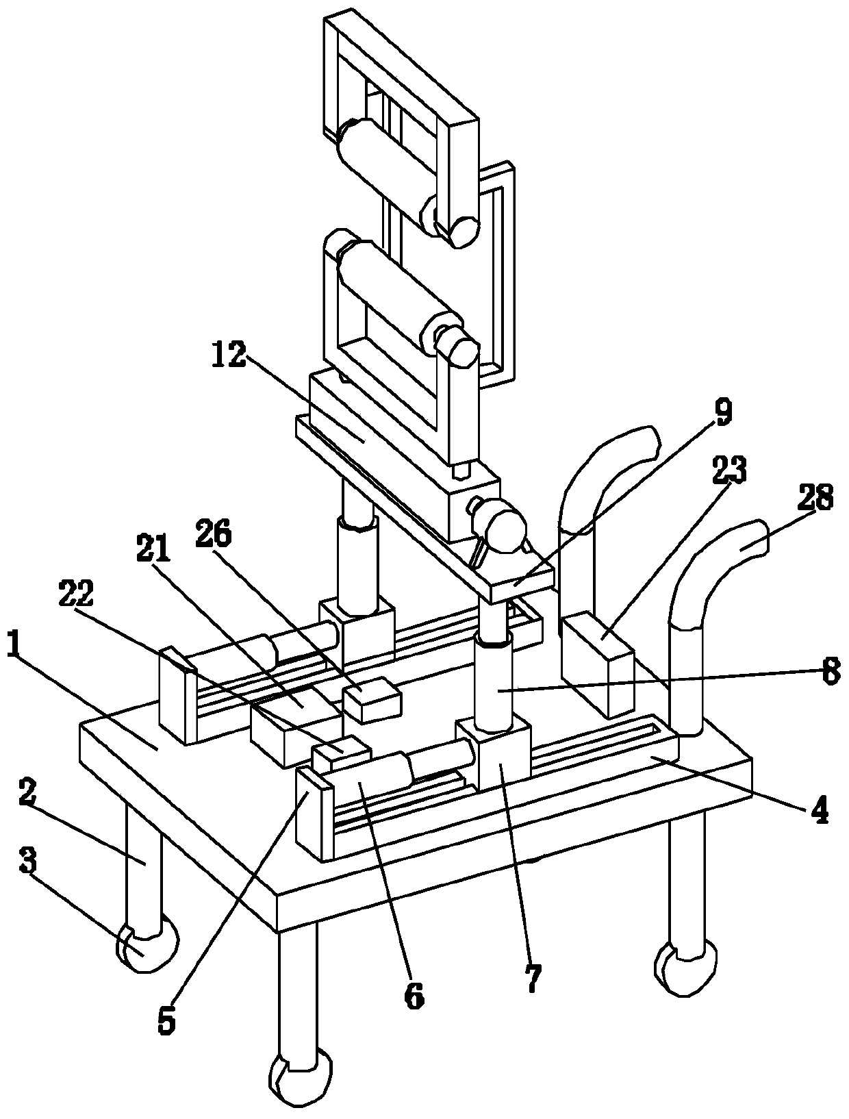
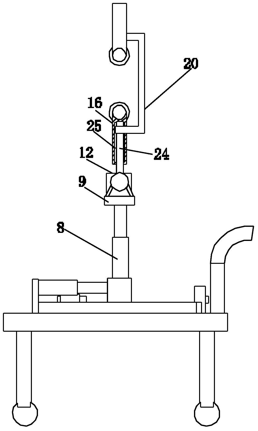
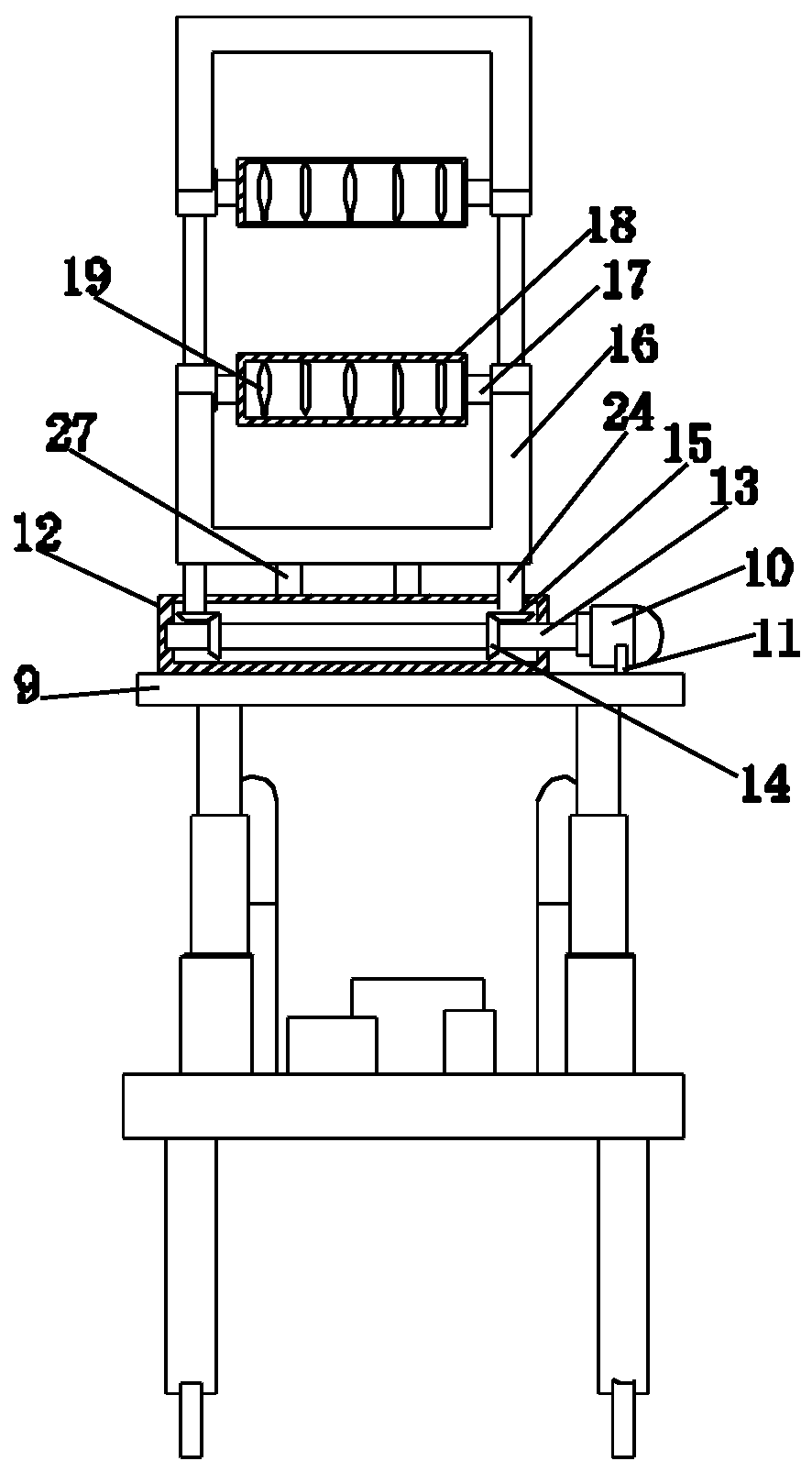
[0017] see Figure 1-3 , the present invention provides a technical solution: a power transmission line deicing device, including a base plate 1, the lower surface of the base plate 1 is evenly distributed around the support 2, the lower end of the support is provided with a universal locking wheel 3, the universal locking wheel The setting of 3 is...


PUM


Abstract

The invention discloses a deicing device for a power transmission line. The device comprises a bottom plate, and at least one sliding table is arranged on the upper surface of the bottom plate. A sliding block is slidably connected into the sliding table. A fixed plate is arranged at one end of the upper surface of the sliding table; the fixed plate is connected with the sliding block through a hydraulic telescopic rod; the upper end of the sliding table is fixedly connected with a supporting plate through a hydraulic lifting column. A fixed box is arranged on the upper surface of the supporting plate; a first rotating shaft is arranged in the fixed box; one end of the first rotating shaft passes through the fixed box and is connected with the output end of a motor; two U-shaped frames arearranged at the upper end of the fixed box; the two U-shaped frames are oppositely arranged; a fixed shaft is arranged in the U-shaped frames; the outer side surface of the fixed shaft is rotatinglyconnected with a roller, and the interior of the roller is provided with an annular heating wire. According to the invention, a deicing operation can be carried out on power transmission lines of different heights, and the damage to the power transmission lines during deicing is avoided; meanwhile, ice blocks between the power transmission lines can be effectively removed, and the deicing convenience is greatly improved.

Description

technical field [0001] The invention relates to the technical field of electric power equipment, in particular to deicing equipment for power transmission lines. Background technique [0002] The icing disaster of transmission lines is one of the main factors that affect the safety of transmission lines in winter. The tower collapsed, causing the transmission line to be paralyzed. [0003] Most of the deicing methods currently used are rigid deicing. The ice on the surface of the transmission line is removed by deicing thorns or deicing shovels. This deicing method is easy to cause damage to the transmission line, and improper operation is easy to pull the transmission line. It causes the power line to fall down, and it is difficult to remove the ice between the power lines. Because some power lines will sink under the pressure of the ice, the commonly used deicing device lacks a height adjustment device, and the scope of application is small. Contents of the invention ...

Claims


Application Information

Patent Timeline
Patent Type & Authority Applications(China)
IPC IPC(8): H02G7/16
CPCH02G7/16
Inventor 裴明军孔凡龙付荣贾雪蒙樊立凤陈亚辉赵亚伟孙云周乐樊毅孟东杰杨哲张建新张捍卫唐东杰樊建国党帅
Owner 国网河南省电力公司新安县供电公司
Why Eureka
Try Eureka