Heat dissipation assembly

A technology for heat dissipation components and liquid cooling, which is applied to electrical components, structural components of electrical equipment, cooling/ventilation/heating renovation, etc., and can solve problems such as increasing cost, increasing design complexity, and increasing chassis size design requirements.

Inactive Publication Date: 2019-12-27
HONG FU JIN PRECISION IND WUHAN CO LTD +1
View PDF6 Cites 0 Cited by
  • Summary
  • Abstract
  • Description
  • Claims
  • Application Information

AI Technical Summary

Problems solved by technology

[0003] In the prior art, a heat exchanger and an axial fan are usually combined to form a heat dissipation assembly, and the assembly is then assembled and fixed on the inside of the system case wall, so the case wall must have a large enough area to accommodate the heat dissipation assembly, so This increases the size design requirements of the chassis, and also limits the application of liquid-cooled radiators in small-sized chassis; especially since the current chassis still use air-cooled heat dissipation as the mainstream, when considering compatibility with liquid-cooled heat dissipation architectures, it is necessary to add several pieces of solid Assembling structural components increases design complexity and increases costs

Method used


Image

  • Heat dissipation assembly
  • Heat dissipation assembly

Examples


Embodiment Construction

[0026] The technical solutions in the embodiments of the present invention will be clearly and completely described below in conjunction with the accompanying drawings in the embodiments of the present invention. Obviously, the described embodiments are part of the embodiments of the present invention, not all of them.

[0027] In order to make the objectives, technical solutions, and advantages of the present invention clearer and more comprehensible, the following will further describe and explain the heat dissipation components of the present invention in detail with reference to the accompanying drawings and embodiments.

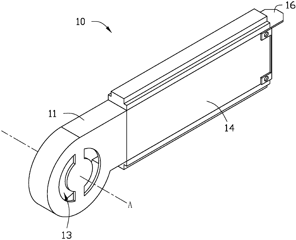
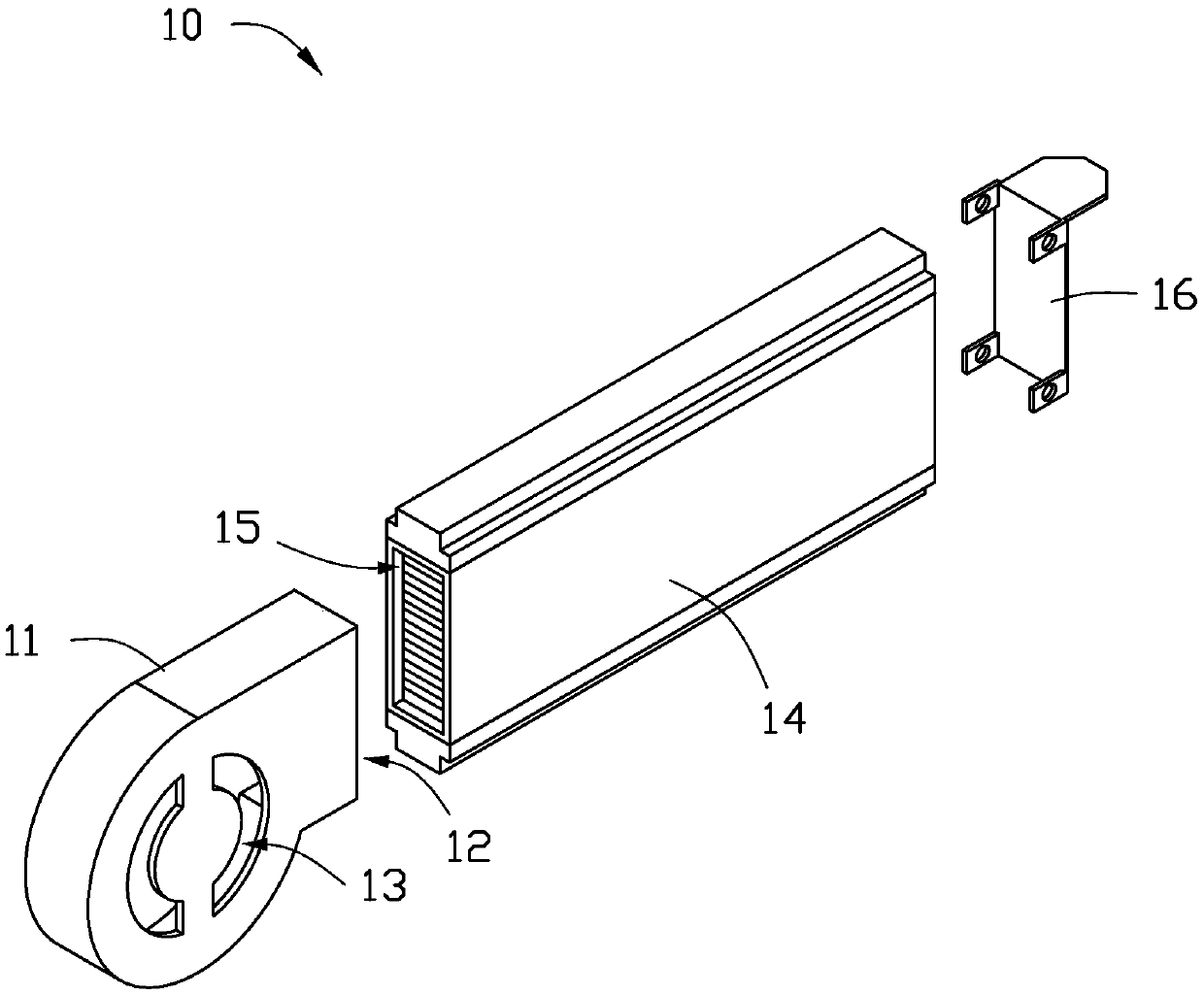
[0028] Please refer to figure 1 and figure 2 In a preferred embodiment of the present invention, a heat dissipation assembly 10 is provided, and the heat dissipation assembly 10 is applied to a liquid-cooled heat dissipation device (not shown).

[0029] The liquid cooling device may further include a liquid cooling head (not shown) and a pump (not shown). Whe...


PUM


Abstract

The invention relates to a heat dissipation assembly. The heat dissipation assembly is applied to a liquid cooling heat dissipation device. The heat dissipation assembly comprises a centrifugal fan and a heat exchanger, wherein the centrifugal fan is provided with an air outlet, the centrifugal fan is used for sucking the air and blowing the air out of the air outlet, the heat exchanger is provided with an air inlet, the air inlet of the heat exchanger is in butt joint with the air outlet of the centrifugal fan, and the airflow blown out of the air outlet of the centrifugal fan is blown to theair inlet of the heat exchanger. The heat dissipation assembly is advantaged in that the heat dissipation assembly of the liquid cooling heat dissipation device is in a card shape, and the adaptability when the liquid cooling heat dissipation device is assembled to a system is improved.

Description

Technical field [0001] The invention relates to a liquid-cooled heat dissipation device, in particular to a heat-dissipating component used in a liquid-cooled heat dissipation device. Background technique [0002] Liquid-cooled heat dissipation technology is a widely used heat dissipation technology in the field of heat dissipation, and liquid-cooled radiators have good heat dissipation effects. Generally speaking, liquid cooling radiators include liquid cooling heads, water pumps, heat exchangers, fans, ducts, and thermal fluids. [0003] In the prior art, a heat exchanger is usually assembled with an axial fan to form a heat dissipation component, and the component is assembled and fixed on the inside of the system chassis wall. Therefore, the chassis wall must have a large enough area to accommodate the heat dissipation component. This increases the size design requirements of the chassis, and restricts the use of liquid-cooled radiators in small-sized chassis; in particular, t...

Claims


Application Information

Patent Timeline
Patent Type & Authority Applications(China)
IPC IPC(8): H05K7/20
CPCH05K7/20136H05K7/20263
Inventor 谢宜莳万崇阳
Owner HONG FU JIN PRECISION IND WUHAN CO LTD
Why Eureka
Try Eureka