Indoor unit for air conditioner

A technology for indoor units and air conditioners, applied in the field of indoor units, can solve the problems of performance degradation, space limitation of air passages, and inability to fully expand the cross-sectional area of ​​air passages, etc., and achieve the effect of improving performance

Active Publication Date: 2019-12-27
DAIKIN IND LTD
View PDF11 Cites 0 Cited by
  • Summary
  • Abstract
  • Description
  • Claims
  • Application Information

AI Technical Summary

Problems solved by technology

[0008] However, when the heat exchanging parts facing each other are arranged in parallel in the indoor unit of an air conditioner equipped with such a U-shaped heat exchanger to blow air in ...

Method used


Image

  • Indoor unit for air conditioner
  • Indoor unit for air conditioner
  • Indoor unit for air conditioner

Examples


no. 1 approach

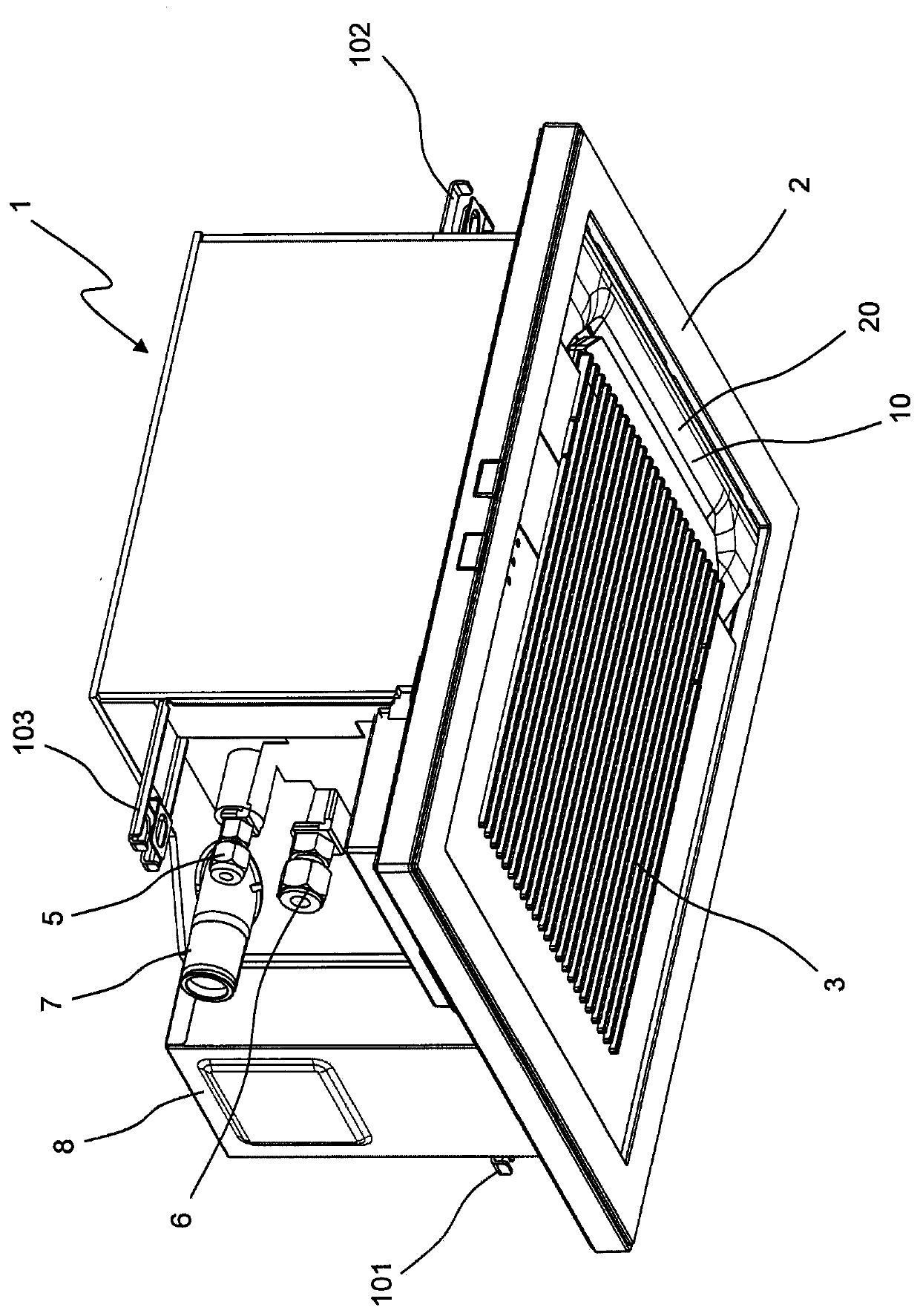
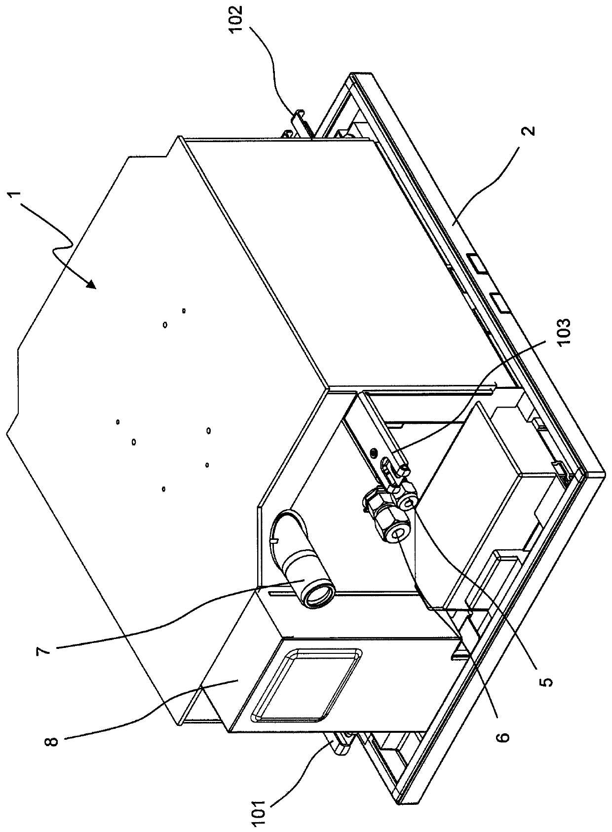
[0070] figure 1 The perspective view which looked at the indoor unit of the air conditioner which concerns on 1st Embodiment of this invention from obliquely below is shown. This indoor unit is a ceiling-embedded indoor unit.

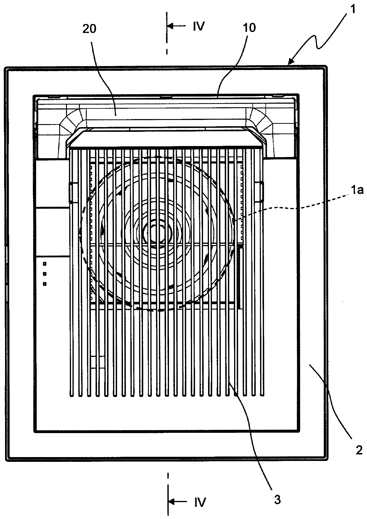
[0071] Such as figure 1 As shown, the indoor unit of the air conditioner according to the first embodiment includes: a casing main body 1; a rectangular panel 2 provided on the lower side of the casing main body 1; and a grille 3 detachably attached to the panel. 2. The casing is formed by using the casing main body 1 , the panel 2 and the grid 3 .

[0072] On the lower surface of the panel 2 , which is one of the longitudinal directions of the panel 2 , an outlet 10 through which the blown air is blown downward is provided along the short side of the panel 2 . In addition, a baffle 20 is rotatably attached to the panel 2 . exist figure 1 In , the state where the air outlet 10 is closed by the baffle 20 is shown.

[0073] In addition, a drain pip...

no. 2 approach

[0121] Figure 15 A bottom view showing a state in which a panel, a drain pan, and the like are removed from an indoor unit of an air conditioner according to a second embodiment of the present invention. The indoor unit of the air conditioner of the second embodiment has the same structure as that of the indoor unit of the air conditioner of the first embodiment except for the U-shaped heat exchanger 140. Figure 1 to Figure 3 .

[0122] Such as Figure 15 As shown, the indoor unit of the air conditioner according to the second embodiment includes a U-shaped heat exchanger 140 in plan view. The heat exchanger 140 includes: a first heat exchange portion 141 arranged parallel to the first wall portion 11 of the housing body 1; a second heat exchange portion 142 connected to one end of the first heat exchange portion 141; and The third heat exchange part 143 is connected to the other end of the first heat exchange part 141 . The second heat exchange portion 142 extends paral...


PUM


Abstract

The indoor unit for an air conditioner is provided with: a casing main body (1); a turbo fan (30) which is disposed in the casing main body (1); a heat exchanger (40) which is disposed in the casing main body (1) so as to surround three sides of the turbo fan (30); a partition plate (50) which connects the two ends of the heat exchanger (40), and which, along with the heat exchanger (40), surrounds the turbo fan (30); and a blow-out port (10) which is provided on the side of the heat exchanger (40) opposite to the partition plate (50) such that blown out air is blown out downwards. The downstream side of an air passage (P) from the heat exchanger (40) to the blow-out port (10) in the casing main body (1) has a cross-sectional shape which has: a first air passage area (Aa) extending along one side of the casing main body (1); and second air passage areas (Ab) which extend from the two ends of the first air passage area (Aa) towards the side of a second wall part (12). Accordingly, an indoor unit for an air conditioner is provided which is capable of reducing pressure loss in the air passage, and improving performance.

Description

technical field [0001] The present invention relates to an indoor unit of an air conditioner. Background technique [0002] In the past, as an indoor unit of an air conditioner, there is a structure as follows: a U-shaped heat exchanger is provided, and the air sucked by a vortex fan is blown out in three directions through the heat exchanger (for example, refer to Japanese Patent Application Laid-Open No. 2002-349890 ( Patent Document 1)). [0003] prior art literature [0004] patent documents [0005] Patent Document 1: Japanese Patent Laid-Open No. 2002-349890 Contents of the invention [0006] The problem to be solved by the invention [0007] According to the above-mentioned indoor unit of the conventional air conditioner, it is preferable that the opposed heat exchange parts of the U-shaped heat exchanger are arranged in parallel. [0008] However, when the heat exchanging parts facing each other are arranged in parallel in the indoor unit of an air conditioner...

Claims


Application Information

Patent Timeline
IPC IPC(8): F24F1/0022F24F1/0063F24F13/22F24F13/30
CPCF24F13/22F24F13/30F24F1/0011F24F13/081F24F1/0047
Inventor 大石康弘土居弘和
Owner DAIKIN IND LTD
Why Eureka
Try Eureka