
Method for replacing floor brush for cleaning for one-key type replacement of roller brush body

A replacement method and technology of rolling brushes, which are applied to cleaning equipment, applications, household appliances, etc., can solve the problems of inability to remove the roller, the rolling brush body falls off, and the rolling brush body is difficult to clean, so as to facilitate cleaning and replacement of the rolling brush body, Reduce maintenance costs and ensure the effect of non-eccentricity

Pending Publication Date: 2019-12-31
SUZHOU CHO ELECTRIC APPLIANCE CO LTD
View PDF5 Cites 5 Cited by
  • Summary
  • Abstract
  • Description
  • Claims
  • Application Information

AI Technical Summary

Problems solved by technology

[0004] 1) The motor and the power transmission assembly are in the middle of the roller brush chamber, and two rollers are installed on the left and right; Under the condition of force, because there is only one-sided limit, it is easy to cause its eccentricity and affect the service life of the ground brush;
[0005] 2) The motor and power transmission components are in the middle of the roller brush chamber, and the air ducts are on both sides. There is only one roller, and the roller cannot be removed, which will limit the use of the floor brush and make it difficult to clean the roller brush body
[0006] 3) The motor is on the rear side of the brush body, the power transmission component is on one side of the brush body, and only one brush body is installed, and the roller brush body can only be removed by removing up and down. Due to the unlocking of this structure On the base, the roller needs to be removed by tools or two-handed operation, which is very inconvenient to disassemble

Method used


Image

  • Method for replacing floor brush for cleaning for one-key type replacement of roller brush body
  • Method for replacing floor brush for cleaning for one-key type replacement of roller brush body
  • Method for replacing floor brush for cleaning for one-key type replacement of roller brush body

Examples


Embodiment 1

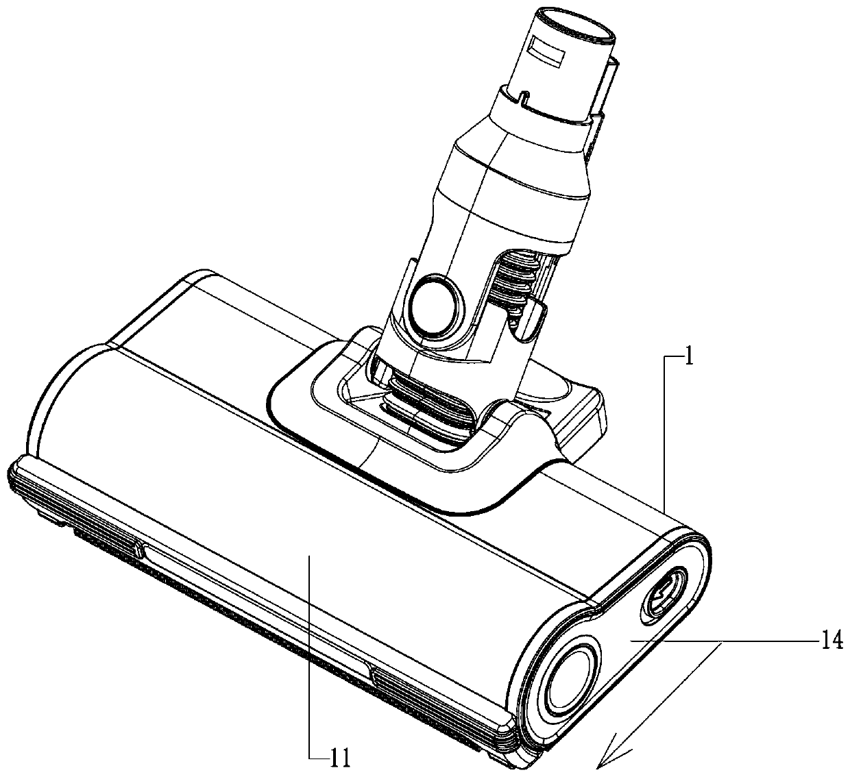
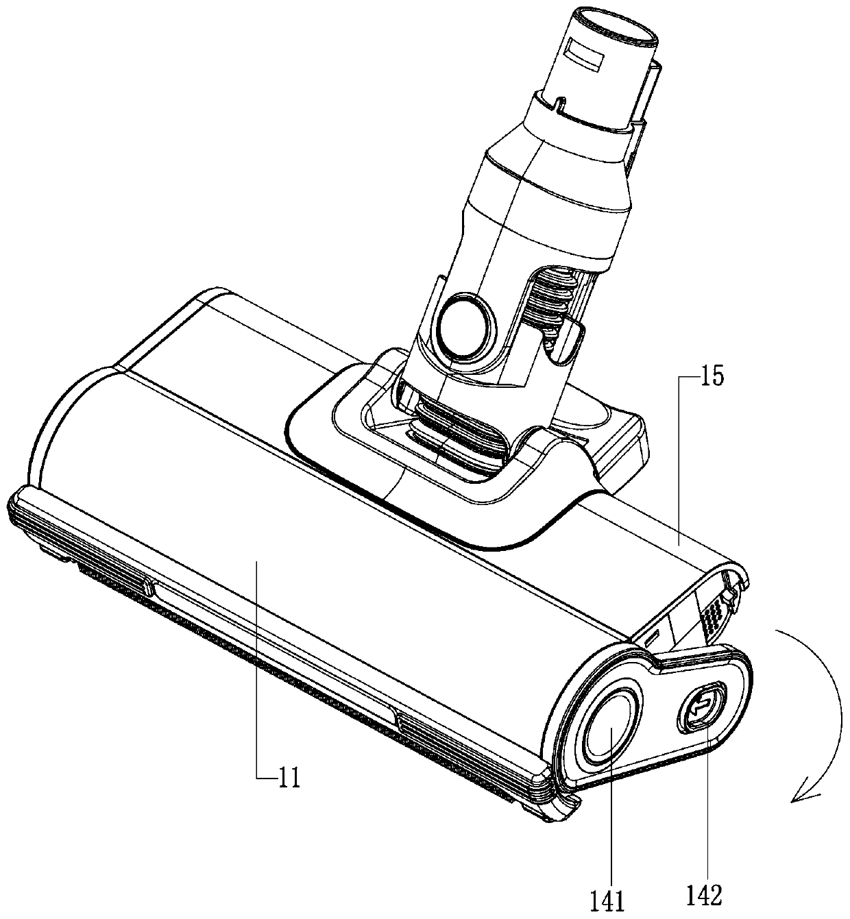
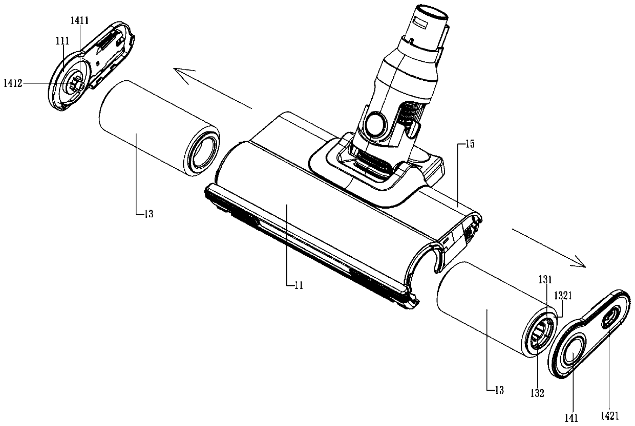
[0035] see Figure 1 to Figure 4 , the figure shows a one-button cleaning floor brush for replacing the rolling brush body provided by the embodiment of the present invention. The rolling brush body 13 and the main body of the transmission assembly 12 are installed in the middle position in the rolling brush chamber 11, and the rolling brush chamber 11 is provided with two symmetrically arranged rolling brush bodies 13, and the inner ends of the two rolling brush bodies 13 are respectively rotatable Connected to the opposite sides of the main body of the transmission assembly 12, the opposite ends of the roller brush chamber 11 are respectively detachably connected with two end covers 14, and the outer end of the roller brush body 13 is rotatably connected to the inner wall of the end cover 14 .

[0036] The main improvement of the floor brush for cleaning with one-button replacement of the rolling brush body provided in this embodiment is that on the basis of setting two rol...

Embodiment 2

[0042] see Figure 1 to Figure 4 , the figure shows a one-button cleaning floor brush for replacing the roller brush body provided by Embodiment 2 of the present invention. This embodiment further makes the following technical solutions as improvements on the basis of the above embodiments: The inner side of the end cover 14 is equipped with a bearing 1411, and the outer end of the roller brush body 13 is provided with a connecting groove 131, and the connecting groove 131 is sleeved on the bearing 1411. A circle of clamping ribs 132 is arranged on the groove wall, and the clamping teeth 1412 are clamped between two adjacent clamping ribs 132 .

[0043] Through the optimized configuration of the above structure, it can be ensured that the end cover realizes stable rotational positioning of the outer end of the roller brush body, which can prevent the roller brush body from falling off and ensure that the roller brush body is not eccentric during operation.

Embodiment 3

[0045] see Figure 1 to Figure 4 , the figure shows a one-button cleaning floor brush for replacing the roller brush body provided by Embodiment 3 of the present invention. This embodiment further makes the following technical solutions as improvements on the basis of the above embodiments: The end cover 14 includes a rotating connection part 141 and a clamping part 142. The rotating connecting part 141 is circular in shape as a whole, and it is rotatably connected to the end of the roller brush chamber 11. The clamping part 142 is clamped to the floor of the floor brush body 1. on the side of the brush housing 15.

[0046] continue to see Figure 1 to Figure 4 , the inner surface of the rotating connection part 141 is provided with an annular convex rib 143, the outer end of the brush body 13 has a convex ring 1321, and the annular rib 143 snaps into the end convex rib 111 and the convex rib of the rolling brush chamber 11. In the gap between circles 1321.

[0047] Continue ...


PUM


Abstract

The invention provides a method for replacing a floor brush for cleaning for one-key type replacement of a roller brush body. The method comprises the following steps: 1) pushing a buckle on a clamping part so as to enable an end cover and a floor brush shell to be unhooked; 2) rotating the end cover, so that the end cover is disengaged from a limiting mechanism of a roller brush bin, and the endcover can be drawn out from the two ends of the roller brush bin in the axial direction respectively; 3) pulling out the roller brush body, so that the roller brush body is separated from a power output shaft, and the roller brush body is pulled away from the roller brush bin; and 4) inserting a new roller brush body into the end part of the roller brush bin, and then sealing the end cover. According to the method in the invention, a one-key type disassembly mode is adopted, the roller brush body can be quickly disassembled only after the end cover is unlocked, and the end cover is positionedat the outer side end of the roller brush body, so that the problem that the current roller brush body is easy to fall off and is easy to be eccentric during operation can be effectively solved.

Description

technical field [0001] The invention relates to the field of cleaning floor brushes, in particular to a method for replacing a cleaning floor brush with a one-button replacement of a rolling brush body. Background technique [0002] In the vertical vacuum cleaners, horizontal vacuum cleaners or washing machines widely used at present, the floor brush part is a more important part, which is connected to the main engine through the dust pipe, and is mainly used for cleaning the floors, carpets and other grounds. [0003] Among the currently used ground brush component structures, the installation structure for the roller brush body mainly includes the following types: [0004] 1) The motor and power transmission components are installed in the middle of the roller brush chamber, and two rollers are installed on the left and right; in this structure, since the outer end of the roller brush is not fixed, it is easy to cause the roller brush body to fall off, and the roller brush...

Claims


Application Information

Patent Timeline
IPC IPC(8): A47L9/04A47L11/24A47L11/32
CPCA47L9/04A47L9/0427A47L11/24A47L11/32
Inventor 邹宗彬
Owner SUZHOU CHO ELECTRIC APPLIANCE CO LTD
Learn More