Concentrate recycling device

A recovery device and concentrate technology, applied to the feed/discharge device of the settling tank, settling tank, chemical instruments and methods, etc., can solve the problems of poor recovery effect, unreasonable feeding structure, etc., and improve the input The effect of improving the material effect, improving the recovery rate, and increasing the sedimentation speed

Pending Publication Date: 2019-12-31
淮北市协力重型机器有限责任公司
View PDF1 Cites 1 Cited by
  • Summary
  • Abstract
  • Description
  • Claims
  • Application Information

AI Technical Summary

Problems solved by technology

[0007] The technical problem to be solved by the present invention is: how to solve the problem of poor recycling effect caused by unreasonable feeding structure

Method used


Image

  • Concentrate recycling device
  • Concentrate recycling device
  • Concentrate recycling device

Examples


Embodiment 1

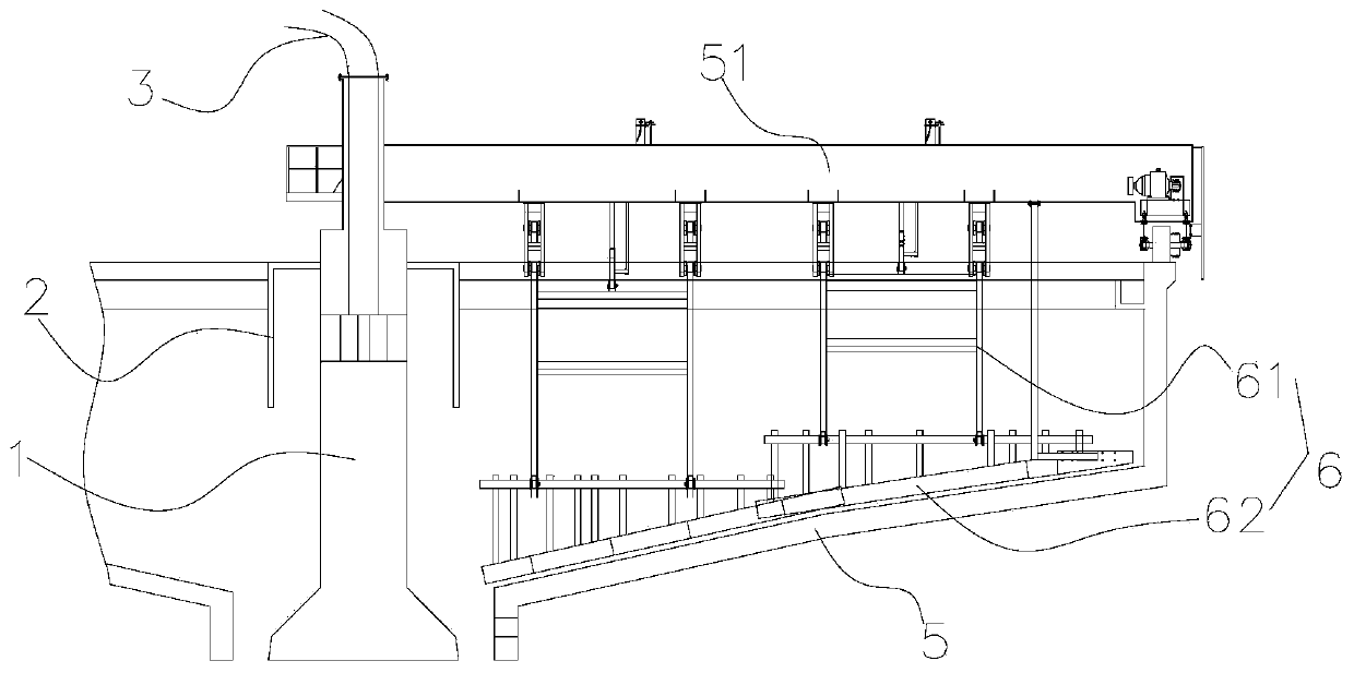
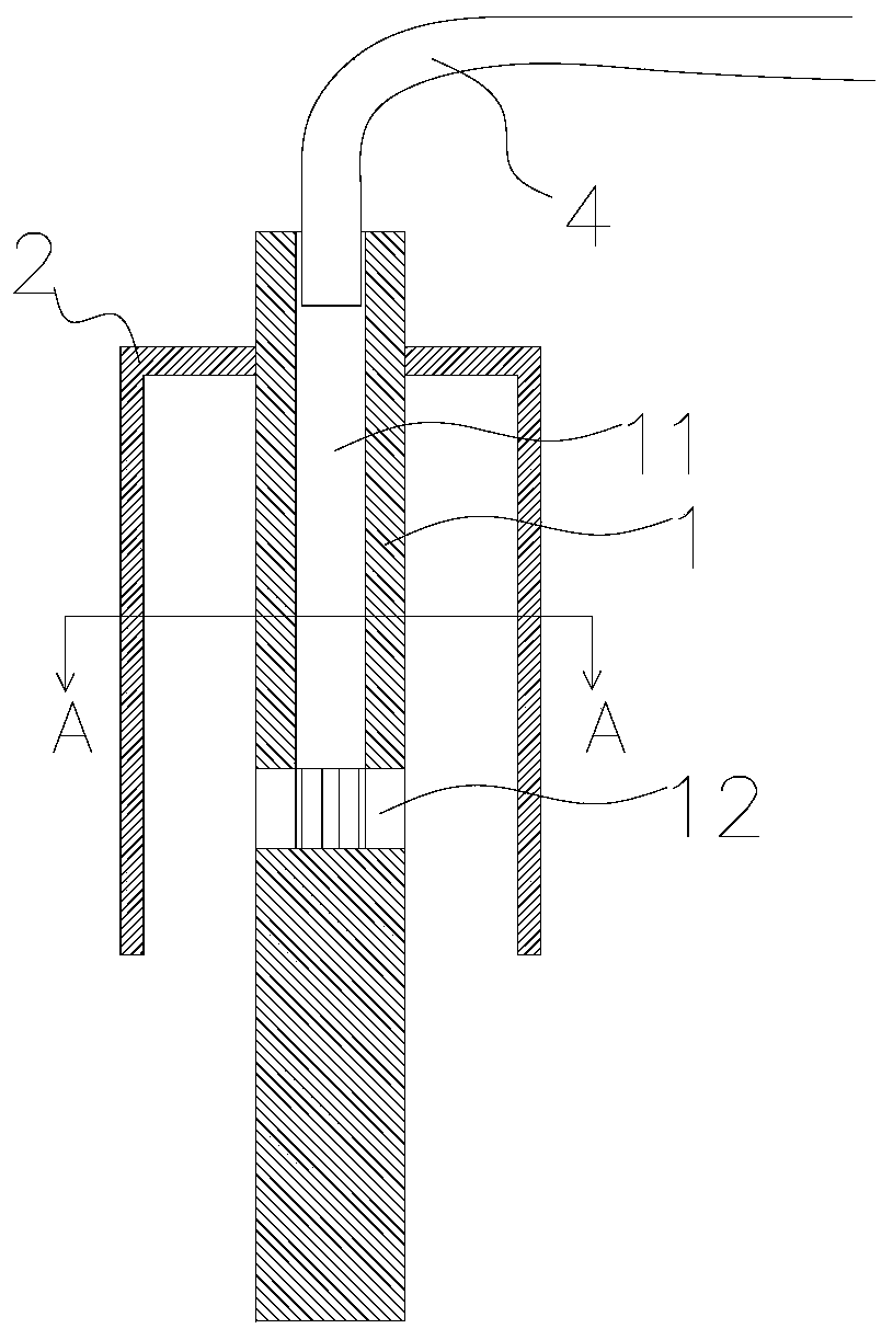
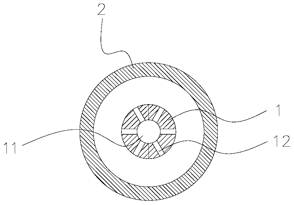
[0047] Such asfigure 1 As shown, a concentrate recovery device includes a concentration tank 5, a feeding mechanism, and the feeding mechanism is fixed in the concentration tank 5. The upper part of the concentration tank 5 is provided with an overflow port, and the bottom is provided with a discharge port. The mechanism includes a feeding solid pipe 1, a steady flow cylinder 2 sleeved outside the feeding solid pipe 1, and a flow guide mechanism 3. Inside the feeding solid pipe 1 is a cavity 11 with an opening at the top, and the opening is the feeding pipe 4 At the access point, the bottom of the cavity is provided with a plurality of discharge holes 12 penetrating with the outside, the steady flow cylinder 2 is set at intervals from the feed solid pipe 1, and the flow guide mechanism 3 is fixed on the feed solid pipe 1, and is in a steady flow Below the cylinder 2, the discharge hole is placed in the turbid layer of the pulp in the thickening tank.

[0048] In this embodimen...

Embodiment 2

[0067] Such as Figure 4 , Figure 5 As shown, the difference between the second embodiment and the first embodiment is that: a flow guiding mechanism 3 is also included.

[0068] In this embodiment, the flow guiding mechanism 3 is a circular frustum structure, and the inside is hollow or solid, not limited to the internal structure.

[0069] The flow direction of the ore pulp is changed by the flow stabilization cylinder 2, and the flow direction is mostly downward, which still produces a certain impact. The flow guide mechanism 3 can change the flow velocity and direction of the ore pulp impacted on the flow stabilization cylinder 2 again, so that the ore pulp The direction of the flow changes to a roughly horizontal direction and enters the turbid layer in a more gradual manner.

Embodiment 3

[0071] Such as Figure 6 As shown, the difference between the third embodiment and the second embodiment is that the setting positions of the feed inlets are different.

[0072] The feed solid pipe 1 is open on the side, and the feed pipe 4 is connected to the opening after passing through the thickener machine wall from the outside of the thickener.

[0073] When feeding, feed pipe 4 can be fixed on the truss.


PUM


Abstract

The invention discloses a concentrate recycling device which comprises a concentration tank and a feeding mechanism, wherein the feeding mechanism is fixed inside the concentration tank; an overflowing hole is formed in the upper part of the concentration tank; a discharge hole is formed in the bottom of the concentration tank; the feeding mechanism comprises a feeding fixed tube and a flow stabilizing cylinder which is connected outside the feeding fixed tube in a sleeving manner; the interior of the feeding fixed tube is a cavity of which the top end or / and a side surface is opened; the opening is a feeding tube access part; a plurality of discharge holes penetrating through the outside are formed in the bottom of the cavity; the flow stabilizing cylinder and the feeding fixed tube are arranged at an interval; the discharge holes are formed in a turbid layer of ore pulp in the concentration tank. The device has the beneficial effects that as the discharge holes are mounted in the turbid layer, a feeding point can be descended, and a clean water layer can be prevented from being turbid; and under a flow chocking function of the flow stabilizing cylinder, the speed of the ore pulpat the discharge holes can be reduced because of the flow stabilizing cylinder, the flowing direction of the ore pulp is also changed, the feeding impact can be reduced, the feeding effect can be improved, the settling speed of a whole settling process can be increased, and the recycling rate can be increased.

Description

technical field [0001] The invention relates to a recovery device, in particular to a concentrate recovery device. Background technique [0002] The ore washing water produced by the metal in the ore washing process still contains some metal particles. Therefore, most of them are recycled to avoid loss. After solid-liquid separation of the ore washing water, a filter cake is obtained. Weigh and distribute the water, make it into a certain concentration of slurry, and then settle it for recycling. For recyclables, in the prior art, physical sedimentation or chemical sedimentation is usually used. Chemical sedimentation usually uses chemical reagents, which is not environmentally friendly. Therefore, more It tends to settle physically; but in the existing physical settlement methods, the thickener is usually used for settlement. The thickener is a thickening chamber with a certain volume. There is a truss on the top of the thickener, and a driving device on the truss. The rod...

Claims


Application Information

Patent Timeline
Patent Type & Authority Applications(China)
IPC IPC(8): B01D21/04B01D21/24
CPCB01D21/04B01D21/2405
Inventor 邵守言赵胜利赵顺利刘航李梅
Owner 淮北市协力重型机器有限责任公司
Why Eureka
Try Eureka