
Iron pipe cutting machine

A cutting machine and iron pipe technology, applied in metal sawing equipment, sawing machine equipment, metal processing equipment and other directions, can solve the problems of many burrs, uneven sections, and different wall thicknesses of iron pipes, and achieve a smooth cutting section. Effect

Pending Publication Date: 2019-12-31
扬州一水机械科技有限公司
View PDF0 Cites 0 Cited by
  • Summary
  • Abstract
  • Description
  • Claims
  • Application Information

AI Technical Summary

Problems solved by technology

[0002] Iron pipe is a relatively common transportation pipeline, which is widely used in industrial applications such as oil pipelines, elbows or bearings. However, due to the long length of iron pipes, iron pipes need to be cut into shorter lengths during use and transportation. One section, for example, can be cut into 50-800mm sections, and due to the different application fields of iron pipes, the wall thickness of iron pipes is also different. At present, there is no matching iron pipe cutting machine. When using other cutting machines to cut iron pipes , there are many burrs on the section, uneven section and other problems

Method used


Image

  • Iron pipe cutting machine
  • Iron pipe cutting machine
  • Iron pipe cutting machine

Examples


Embodiment 1

[0022] Embodiment 1: An iron pipe cutting machine, including: a feeding part, a cutting part and a clamping part, wherein,

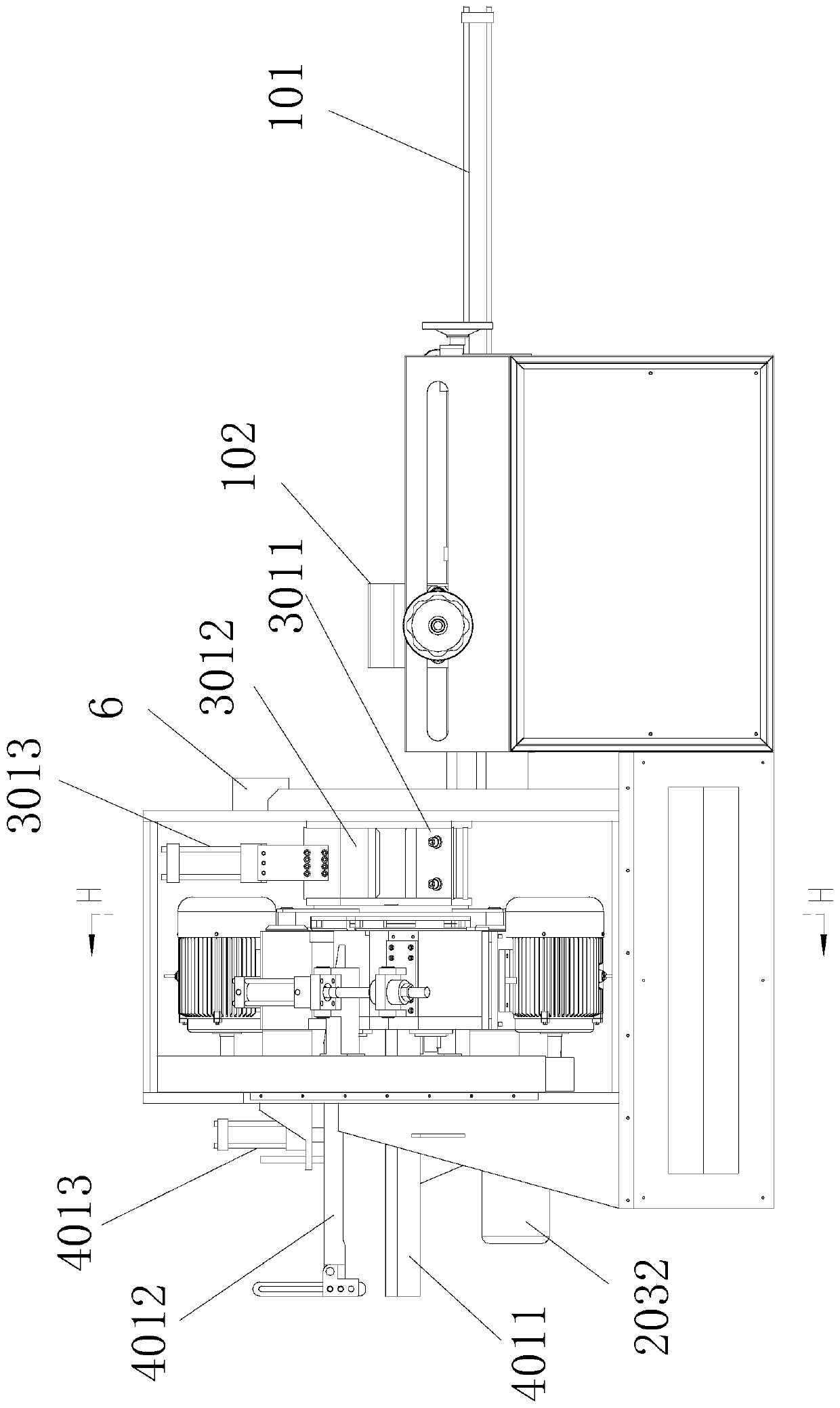
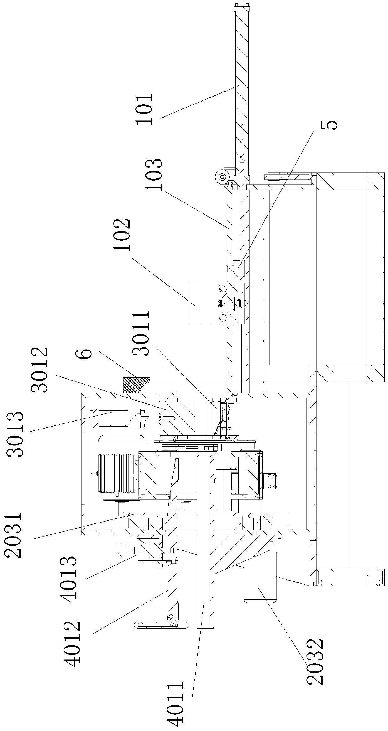
[0023] like figure 1 and figure 2 As shown, the feeding part includes a driving part 101 and a feeding clamping part 102, and the driving part 101 drives the feeding clamping part 102 to reciprocate. In this application, the feeding clamping part 102 is a feeding clamp, which drives Part 101 is a feed oil cylinder, one end of the feed clamp is connected to the feed cylinder, the feed clamp is arranged on the guide rail of the frame, and the feed clamp moves along the guide rail 103 under the drive of the feed cylinder; the feed clamp Specifically, it includes two opposite half clamps 1021, and each half clamp corresponds to a feed clamp cylinder 1022. Under the action of the feed clamp cylinder, the two half clamps move closer to each other or separate from each other. , when it is necessary to clamp the iron pipe for feeding, the two half clamps move...

Embodiment 2

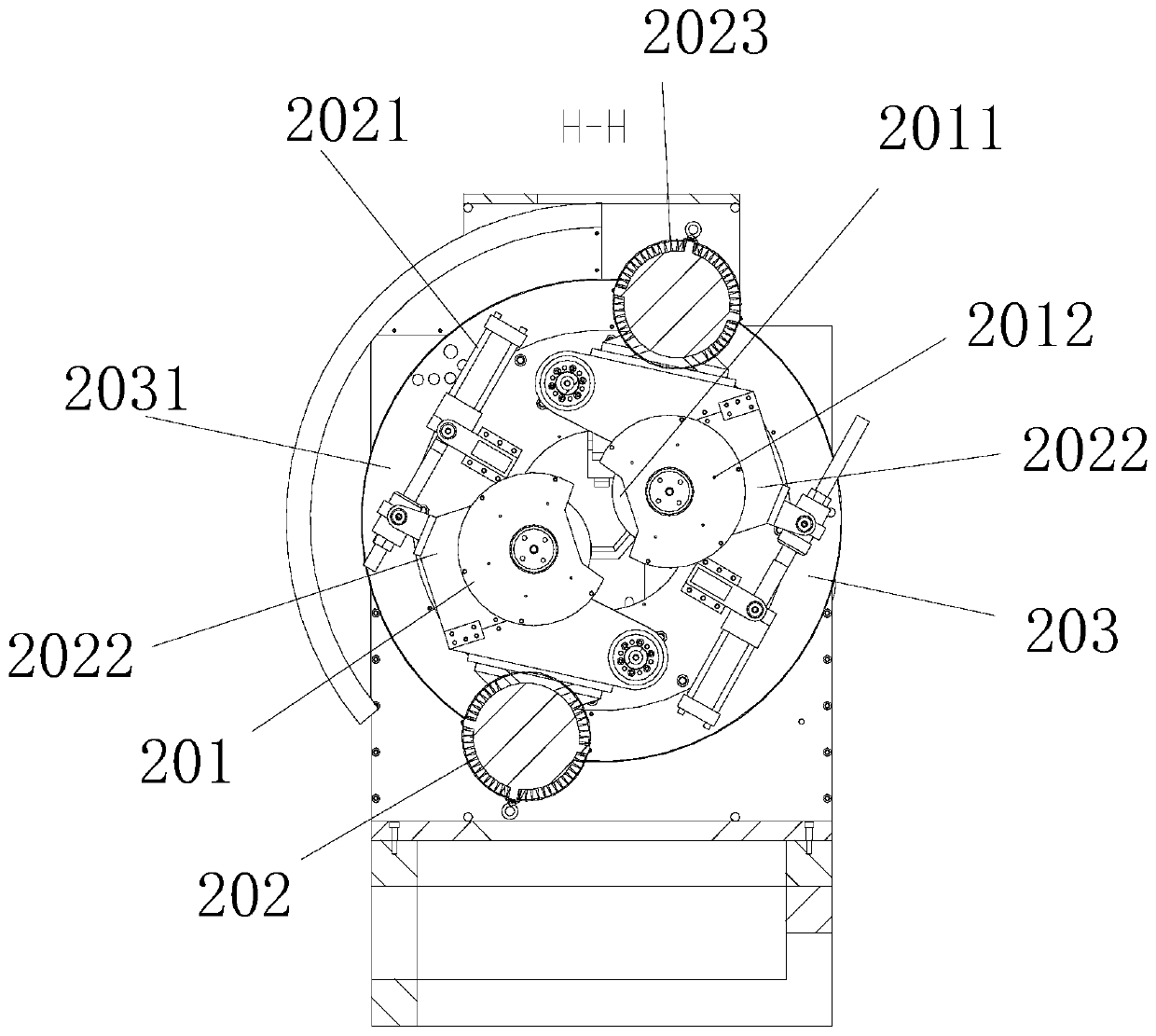
[0027] Embodiment 2: The applicant makes a further design on the basis of Embodiment 1. In order to improve the cutting efficiency, in this embodiment, the cutting parts 201 and the cutting drive part 202 are two groups, and the two groups of cutting parts are arranged opposite to each other. The piece 201 includes a saw blade 2011 and a saw blade guard 2012. The saw blade guard 2012 is sleeved on the saw blade 2011, and the saw blade guard 2012 is provided with a hole for the saw blade to extend out. In this embodiment Using TCT cold saw blade, the diameter can be adjusted Iron pipes with a thickness of 15mm-30mm are cut at high speed. When cutting, the cutting blade driving motor 2023 is started, and the reduction box 2022 is driven to drive the saw blade 2011 in the cutting part 201 to rotate, so as to realize the contact between the saw blade 2011 and the iron pipe to realize cutting; after the saw blade is started, the feed cylinder is started , drive the reduction box ...

Embodiment 3

[0028] Embodiment three: as Figure 4 As shown, the applicant made further research and development on the basis of Embodiment 1 or Embodiment 2. The side guide rail 103 of the feed clamp is also provided with a fixed-length limit seat 4, and the fixed-length limit seat 4 is located at Near the side of the feed oil cylinder, since the feed clamp and the fixed-length limit seat 5 are all arranged on the guide rail 103, and the length of the guide rail is constant, the feed clamp is placed on the guide rail through the fixed-length limit seat. The location of the position is limited, that is, the distance between the feeding clamp and the cutting part is limited. By controlling the distance between the feeding clamp and the cutting part, the length of each iron pipe entering the cutting part is controlled, and the length of the iron pipe is realized. Precise control.

[0029] In this embodiment, a metal non-destructive flaw detection device 6 is also provided between the feedin...


PUM

PropertyMeasurementUnit
Thicknessaaaaaaaaaa

Abstract

The invention relates to an iron pipe cutting machine. The machine comprises a feeding part, a cutting part and a clamping part, wherein the feeding part comprises a driving part and a feeding clamping piece, the driving part drives the feeding clamping piece to reciprocate, the cutting part comprises cutting pieces, a cutting driving part and a rotating part, the cutting driving part is arrangedat one side of the cutting pieces, the cutting pieces are driven to operate through the cutting driving part, the two cutting pieces are arranged, the rotating part comprises a rotary cutter disc anda rotary driving part, the cutting pieces are arranged on the rotary cutter disc, the rotary cutter disc is driven to rotate through the rotary driving part, the clamping part comprises a front clamping part and a rear clamping part, the two cutting pieces simultaneously cut an iron pipe, and the cutting pieces can be rotated by 180 degrees, so that the 360-degree cutting on the iron pipe is achieved, a cutting section is flat and smooth, the iron pipe is cut by adopting a cold saw blade, and the cutting section is free of burrs; and the machine can be used for cutting the iron pipe with the diameter of 110-220 mm and the wall thickness of 10-30 mm, and the cutting can be completed within 1 minute.

Description

technical field [0001] The invention relates to a cutting machine, in particular to an iron pipe cutting machine. Background technique [0002] Iron pipe is a relatively common transportation pipeline, which is widely used in industrial applications such as oil pipelines, elbows or bearings. However, due to the long length of iron pipes, iron pipes need to be cut into shorter lengths during use and transportation. One section, for example, can be cut into 50-800mm sections, and due to the different application fields of iron pipes, the wall thickness of iron pipes is also different. At present, there is no matching iron pipe cutting machine. When using other cutting machines to cut iron pipes , there are many burrs in the section, and the section is uneven. Contents of the invention [0003] In order to overcome the above defects, the present invention provides a special iron pipe cutting machine for iron pipes. [0004] The technical solution adopted by the present inve...

Claims


Application Information

Patent Timeline
IPC IPC(8): B23D45/12B23D45/10B23D47/04B23D47/10
CPCB23D45/10B23D45/12B23D47/04B23D47/042B23D47/10
Inventor 殷安民王艳良唐永平
Owner 扬州一水机械科技有限公司
Learn More