Machining device and method under laser-induced material coupling reaction

A coupled reaction, laser-induced technology, used in laser welding equipment, metal processing equipment, manufacturing tools, etc., can solve the problems of shortening the service life of the micro-milling tool, wear of the micro-milling tool, low fracture toughness, etc., and improve the quality of the machined surface. and microstructure service performance, the effect of prolonging the service life

Active Publication Date: 2019-12-31
NANJING UNIV OF AERONAUTICS & ASTRONAUTICS
View PDF3 Cites 8 Cited by
  • Summary
  • Abstract
  • Description
  • Claims
  • Application Information

AI Technical Summary

Problems solved by technology

[0003] However, during the processing of ceramic microstructures, due to the high hardness, high brittleness, and low fracture toughness of ceramics, the micro-milling cutters for processing ceramics are severely worn, which greatly shortens the service life of micro-milling cutters.

Method used


Image

  • Machining device and method under laser-induced material coupling reaction
  • Machining device and method under laser-induced material coupling reaction

Examples


Embodiment 1

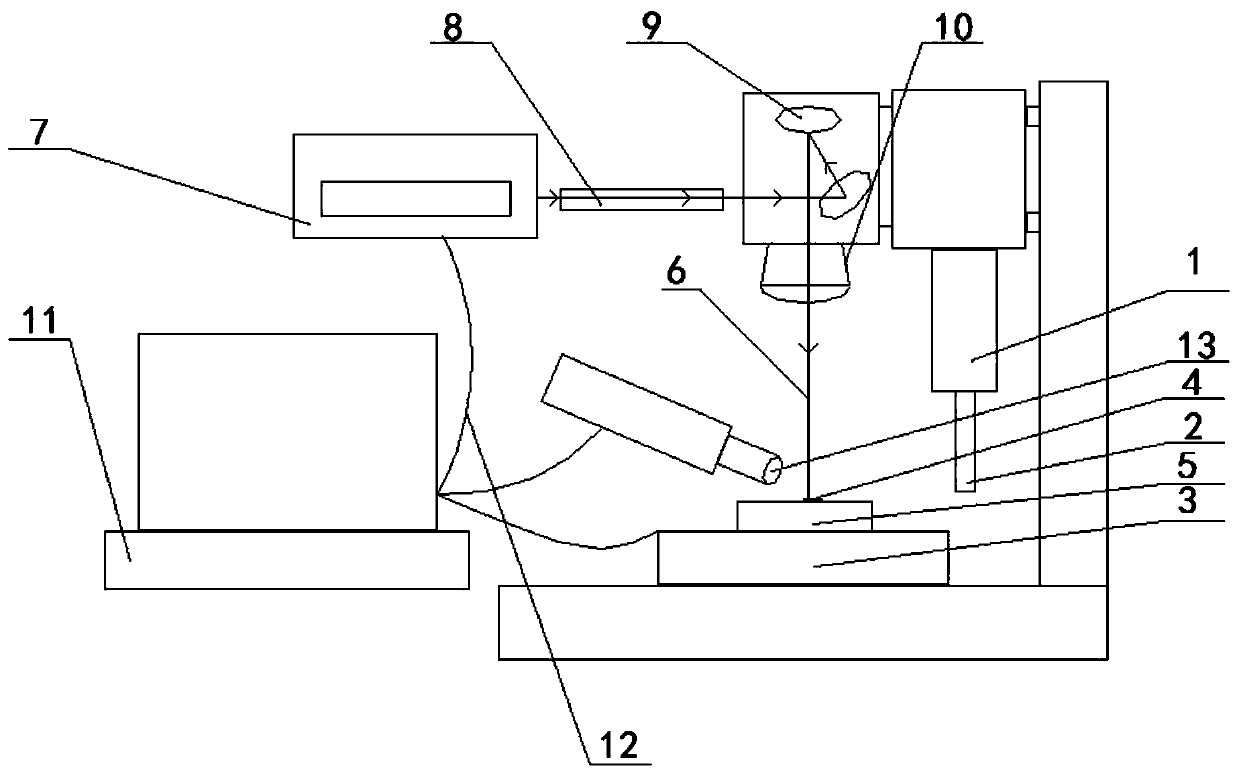
[0033] figure 1 It is a device structure diagram of an embodiment of the processing device under the laser-induced material coupling reaction of the present invention.

[0034] see figure 1 The processing device under the laser-induced material coupling reaction includes: a laser generating device, a milling machine processing device, and the milling machine processing device includes a spindle 1, a micro milling cutter 2 and a workbench 3;

[0035] The laser generating device, the main shaft 1 and the micro milling cutter 2 are all located above the workbench 3; the micro milling cutter 2 is fixed on the main shaft 1; the laser generating device and the micro milling cutter The knives are all facing the workbench 3;

[0036] The workbench 3 is used to place or fix the workpiece 5 whose surface to be processed is coated with the coupling reaction material 4; the laser generating device is used to generate a laser 6 with a power lower than 6W to irradiate the surface to be pr...

Embodiment 2

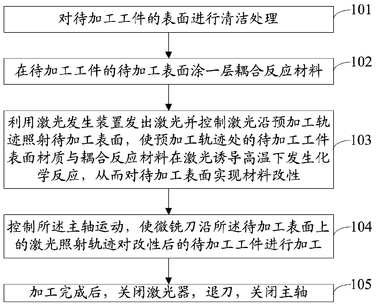
[0049] figure 2 It is a method flow chart of an embodiment of the processing method under the laser-induced material coupling reaction of the present invention.

[0050] The processing method under the laser-induced material coupling reaction is applied to the above-mentioned milling processing device under the laser-induced material coupling reaction.

[0051] see figure 2 , the processing method includes:

[0052] Step 101: Cleaning the surface of the workpiece to be processed. Specifically: the workpiece to be processed is ground, then polished with a polishing agent, and then ultrasonically cleaned in an anhydrous ethanol solution to remove impurities and organic stains on the surface of the workpiece to be processed.

[0053] Step 102: Coating a layer of coupling reaction material on the surface of the workpiece to be processed; the coupling reaction material is a material that chemically reacts with the workpiece when heated by the laser.

[0054] Step 103: Use the...

Embodiment 3

[0066] Alumina ceramics are used as the workpiece to be processed, silica gel or water-coated glass as the coupling reaction material, and a YLP pulsed fiber laser as the laser, using a laser-fine compound machine tool, and adopting the method of layer-by-layer modification-layer-by-layer removal, to the scheme of the present invention for further clarification.

[0067] Under the coupling effect of laser-induced high temperature and coupling reaction materials, alumina ceramics and coupling reaction materials will undergo a rapid chemical reaction to form easily removable silicate and the heat released during the reaction process will lead to a loose and porous structure on the surface layer, thus making The surface to be processed is transformed into a loose and easy-to-remove metamorphic layer in a very short period of time, and then the metamorphic layer and a small amount of subsurface material are quickly removed using a micro-milling cutter. Since the removal amount of ...


PUM

PropertyMeasurementUnit
widthaaaaaaaaaa
widthaaaaaaaaaa

Abstract

The invention discloses a machining device and method under a laser-induced material coupling reaction. The machining device comprises a laser generation device and a milling machine machining device;the milling machine machining device comprises a spindle, a micro-milling cutter and a working table; the laser generation device, the spindle and the micro-milling cutter are all located on the upper part of the working table; the micro-milling cutter is fixed to the spindle; the laser generation device and the micro-milling cutter both directly face the working table; the working table is usedfor storing or fixing to-be-machined workpieces with to-be-machined surfaces coated with coupling reaction materials; the laser generation device is used for generating a laser with the power being less than 6W and irradiating the laser to the to-be-machined surfaces; the micro-milling cutter is used for machining the to-be-machined workpieces along the laser trajectory of the to-be-machined surfaces; and the coupling reaction materials are materials chemically reacting with the to-be-machined workpieces during laser heating. According to the machining device and method, the workpiece machining efficiency, surface quality and three-dimensional microstructure causativity performance can be improved, and the service life of the micro-milling cutter is prolonged.

Description

technical field [0001] The invention relates to the field of advanced manufacturing, in particular to a processing device and method under laser-induced coupling reaction of materials. Background technique [0002] Ceramic materials have excellent properties such as high temperature resistance, wear resistance, corrosion resistance, and ablation resistance. They can withstand harsh working environments that metal materials and polymer materials are incapable of. They are widely used in energy, aerospace, automobiles, metallurgy, chemicals, electronics, etc. field. For example, in the field of electronics industry, ceramic microgroove is an important structure in the heat dissipation device of ceramic flat heat pipe and ceramic resistor system; in the field of aerospace, ceramic microstructure can be used as the hydrodynamic pressure groove of ceramic sealing ring; in the field of biomedicine, Ceramic microstructures serve as surface hydrophobic structures on dentures. Cera...

Claims


Application Information

Patent Timeline
Patent Type & Authority Applications(China)
IPC IPC(8): B23P23/04
CPCB23K26/0093
Inventor 赵国龙夏宏军李亮何宁郝秀清陈妮杨吟飞赵威
Owner NANJING UNIV OF AERONAUTICS & ASTRONAUTICS
Why Eureka
Try Eureka