A processing device and method under laser-induced material coupling reaction
A coupled reaction, laser-induced technology, used in metal processing equipment, laser welding equipment, manufacturing tools, etc., can solve the problems of shortening the service life of the micro-milling tool, wear of the micro-milling tool, low fracture toughness, etc., and improve the quality of the machined surface. and microstructure service performance, the effect of prolonging the service life
- Summary
- Abstract
- Description
- Claims
- Application Information
AI Technical Summary
Problems solved by technology
Method used
Image
Examples
Embodiment 1
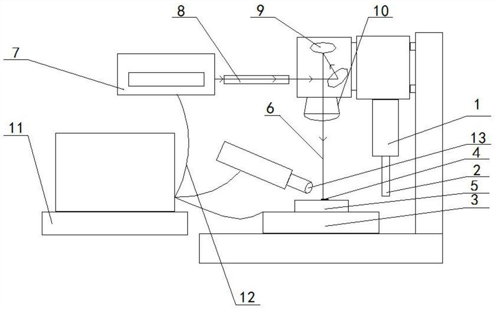
[0033] figure 1 It is a device structure diagram of an embodiment of the processing device under the laser-induced material coupling reaction of the present invention.
[0034] see figure 1 The processing device under the laser-induced material coupling reaction includes: a laser generating device, a milling machine processing device, and the milling machine processing device includes a spindle 1, a micro milling cutter 2 and a workbench 3;
[0035] The laser generating device, the main shaft 1 and the micro milling cutter 2 are all located above the workbench 3; the micro milling cutter 2 is fixed on the main shaft 1; the laser generating device and the micro milling cutter The knives are all facing the workbench 3;
[0036] The workbench 3 is used to place or fix the workpiece 5 whose surface to be processed is coated with the coupling reaction material 4; the laser generating device is used to generate a laser 6 with a power lower than 6W to irradiate the surface to be pr...
Embodiment 2
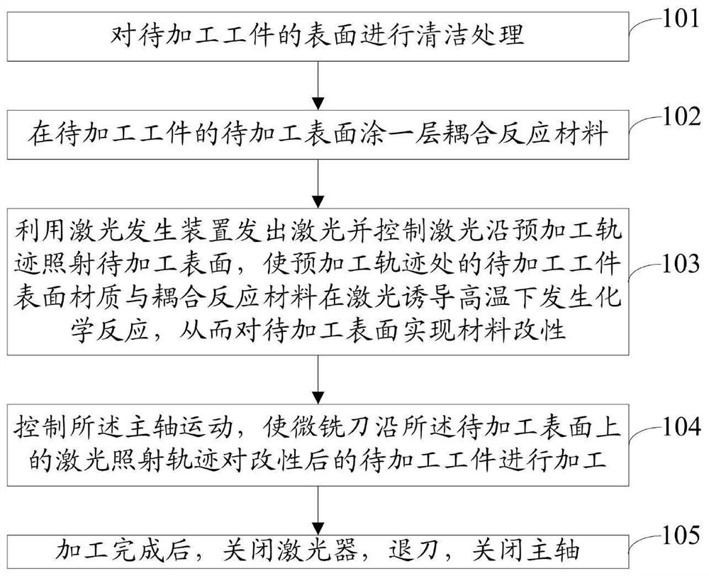
[0049] figure 2 It is a method flow chart of an embodiment of the processing method under the laser-induced material coupling reaction of the present invention.
[0050] The processing method under the laser-induced material coupling reaction is applied to the above-mentioned milling processing device under the laser-induced material coupling reaction.
[0051] see figure 2 , the processing method includes:
[0052] Step 101: Cleaning the surface of the workpiece to be processed. Specifically: the workpiece to be processed is ground, then polished with a polishing agent, and then ultrasonically cleaned in an anhydrous ethanol solution to remove impurities and organic stains on the surface of the workpiece to be processed.
[0053] Step 102: Coating a layer of coupling reaction material on the surface of the workpiece to be processed; the coupling reaction material is a material that chemically reacts with the workpiece when heated by the laser.
[0054] Step 103: Use the...
Embodiment 3
[0066] Alumina ceramics are used as the workpiece to be processed, silica gel or water-coated glass as the coupling reaction material, and a YLP pulsed fiber laser as the laser, using a laser-fine compound machine tool, and adopting the method of layer-by-layer modification-layer-by-layer removal, to the scheme of the present invention for further clarification.
[0067] Under the coupling effect of laser-induced high temperature and coupling reaction materials, alumina ceramics and coupling reaction materials will undergo a rapid chemical reaction to form easily removable silicate and the heat released during the reaction process will lead to a loose and porous structure on the surface layer, thus making The surface to be processed is transformed into a loose and easy-to-remove metamorphic layer in a very short period of time, and then the metamorphic layer and a small amount of subsurface material are quickly removed using a micro-milling cutter. Since the removal amount of ...
PUM
| Property | Measurement | Unit |
|---|---|---|
| width | aaaaa | aaaaa |
| width | aaaaa | aaaaa |
Abstract
Description
Claims
Application Information
 - R&D
- Intellectual Property
- Life Sciences
- Materials
- Tech Scout
- Unparalleled Data Quality
- Higher Quality Content
- 60% Fewer Hallucinations
Browse by: Latest US Patents, China's latest patents, Technical Efficacy Thesaurus, Application Domain, Technology Topic, Popular Technical Reports.
© 2025 PatSnap. All rights reserved.Legal|Privacy policy|Modern Slavery Act Transparency Statement|Sitemap|About US| Contact US: help@patsnap.com


