Auxiliary strain gauge adhering device

A patch device and strain gauge technology, which is applied in the direction of material gluing, connecting components, mechanical equipment, etc., can solve the problems of high accuracy and achieve high accuracy, high reliability, and high alignment

Pending Publication Date: 2019-12-31
SOUTHWEST JIAOTONG UNIV +1
View PDF2 Cites 2 Cited by
  • Summary
  • Abstract
  • Description
  • Claims
  • Application Information

AI Technical Summary

Problems solved by technology

[0005] The purpose of the present invention is to provide a strain gauge auxiliary patching device, which can effectivel

Method used


Image

  • Auxiliary strain gauge adhering device
  • Auxiliary strain gauge adhering device
  • Auxiliary strain gauge adhering device

Examples


Embodiment Construction

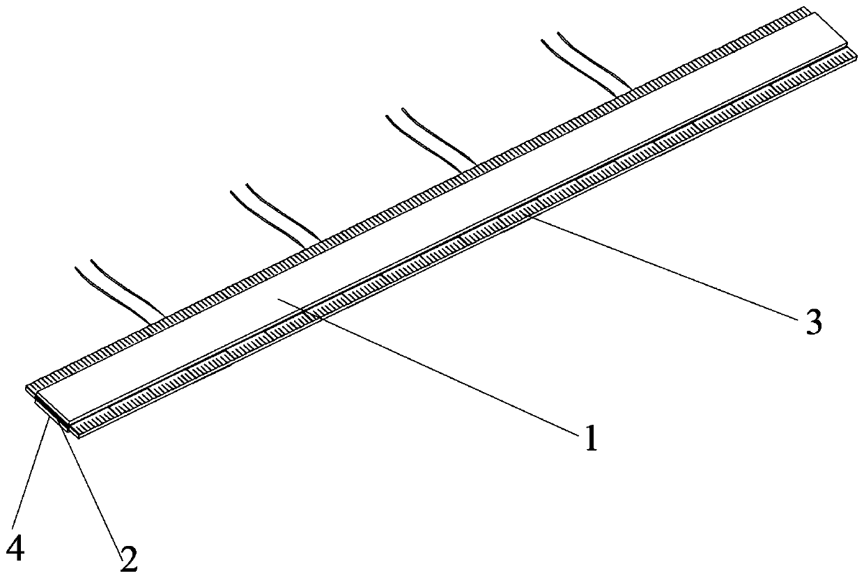
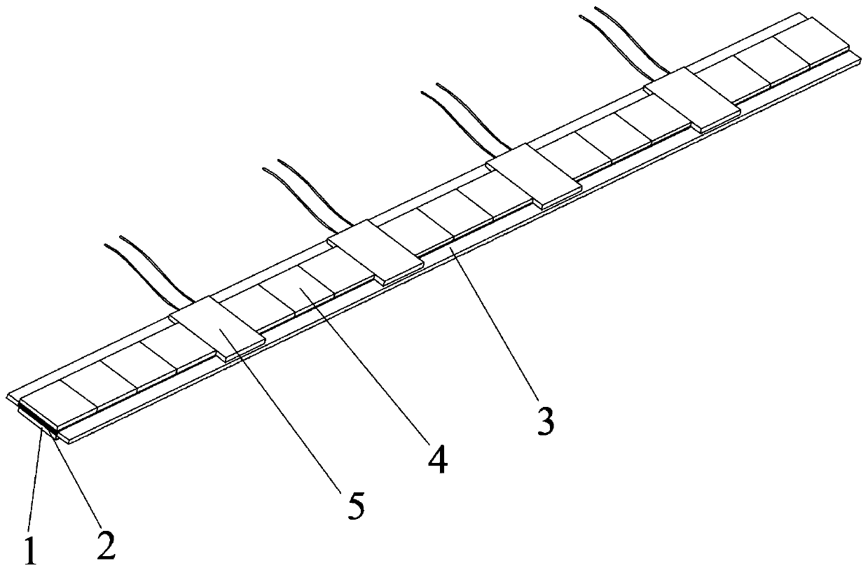
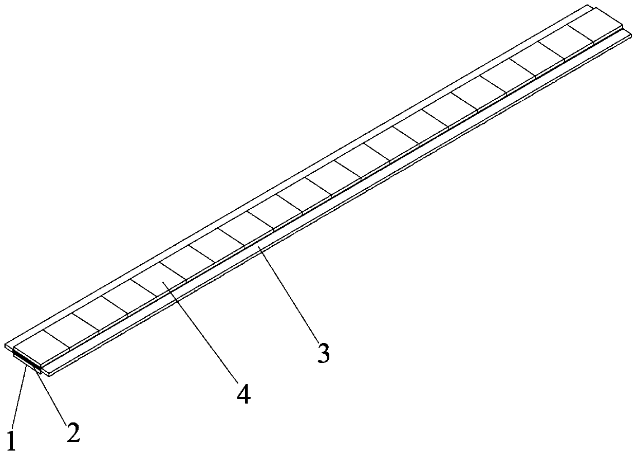
[0013] like figure 1 As shown, a strain gauge auxiliary patching device includes an upper isolation film 1, an adhesive layer 2, a film scale bar 3, a lower isolation film 4 and a strain gauge 5, and is characterized in that the upper isolation film 1 is located at the outermost layer and is connected with the The adhesive layer 2 is bonded and fixed, and the lower isolation film 4 is located at the bottom layer and is also bonded and fixed with the adhesive layer 2. The lower isolation film 4 is a small grid-shaped isolation film. Film scale bars 3 with scales are arranged on both sides of the adhesive layer 2 . The back of the strain gauge 5 is bonded and fixed to the adhesive layer 2 after peeling off the small grid isolation film of the lower layer. The upper isolation film 1 is a monolithic isolation film, and the lower isolation film 4 is a small grid-shaped isolation film. The adhesive layer 2 is sandwiched between the upper isolation film 1 and the lower isolation fi...


PUM


Abstract

The invention provides an auxiliary strain gauge adhering device, and belongs to the technical field of component testing. The auxiliary strain gauge adhering device comprises an upper isolation film,an adhesive layer, thin film scale bars, a lower isolation film, and a strain gauge, and is characterized in that the upper isolation film is located at the outermost layer and is adhered and fixed to the adhesive layer; the lower isolation film is located at the bottom layer and is also adhered and fixed to the adhesive layer; the upper isolation film is a monolithic isolation film; the lower isolation film is a small grid-shaped isolation film; the adhesive layer is sandwiched between the upper isolation film and the lower isolation film; and the upper isolation film and the lower isolationfilm can be peeled off. The thin film scale bars with scales are arranged at the two sides of the adhesive layer; and the thin film scale bars are transparent thin film and have no adhesive. The backof the strain gauge is adhered and fixed to the adhesive layer by peeling off the lower small grid-shaped isolation film. The adhesive layer, the upper isolation film and the lower isolation film areall flexible materials. The auxiliary strain gauge adhering device is used for the testing of component strain or deformation.

Description

technical field [0001] The invention relates to the technical field of component testing, in particular to a strain gauge auxiliary patching device. Background technique [0002] In order to accurately measure the stress and deformation of mechanical structural parts, the commonly used method is to stick strain gauges on the parts, and indirectly measure the deformation and strain of the object by measuring the deformation and resistance changes of the strain gauges. Traditional strain gauges are pasted manually. Generally, the plane of the strain gauge area is first polished and smooth, and the bottom surface of the strain gauge and the concrete patch are evenly coated with epoxy resin, and the end of the strain gauge is clamped with tweezers. Stick it on the patch position of the concrete, and then cover a layer of polyvinyl chloride film on the strain gauge, squeeze it hard along the direction of the strain gauge patch, and press it tightly with your fingers until the str...

Claims


Application Information

Patent Timeline
IPC IPC(8): F16B11/00
CPCF16B11/006
Inventor 阳光武郭蕾宋元全杨龙肖守讷杨冰朱涛王明猛
Owner SOUTHWEST JIAOTONG UNIV
Why Eureka
Try Eureka