Sealing device and hub driving device

A technology of sealing device and sealing lip, which is applied in the direction of transmission parts, engine sealing, engine components, etc., can solve the problems of large instantaneous impact of sealing lip, insufficient spring force, and affecting dynamic sealing effect, etc.

Pending Publication Date: 2019-12-31
SCHAEFFLER TECH AG & CO KG
View PDF0 Cites 0 Cited by
  • Summary
  • Abstract
  • Description
  • Claims
  • Application Information

AI Technical Summary

Problems solved by technology

The elastic force of the spring should not be too large, otherwise it will cause excessive deformation of the sealing lip and affect the dynamic sealing effect
However, in the case of a large shaft runout, the instantaneous impact of the shaft on the sealing lip is very large, which is likely to overcome the elastic force of the spring, causing the sealing lip to separate from the shaft, and thus the seal fails

Method used


Image

  • Sealing device and hub driving device
  • Sealing device and hub driving device
  • Sealing device and hub driving device

Examples


Embodiment Construction

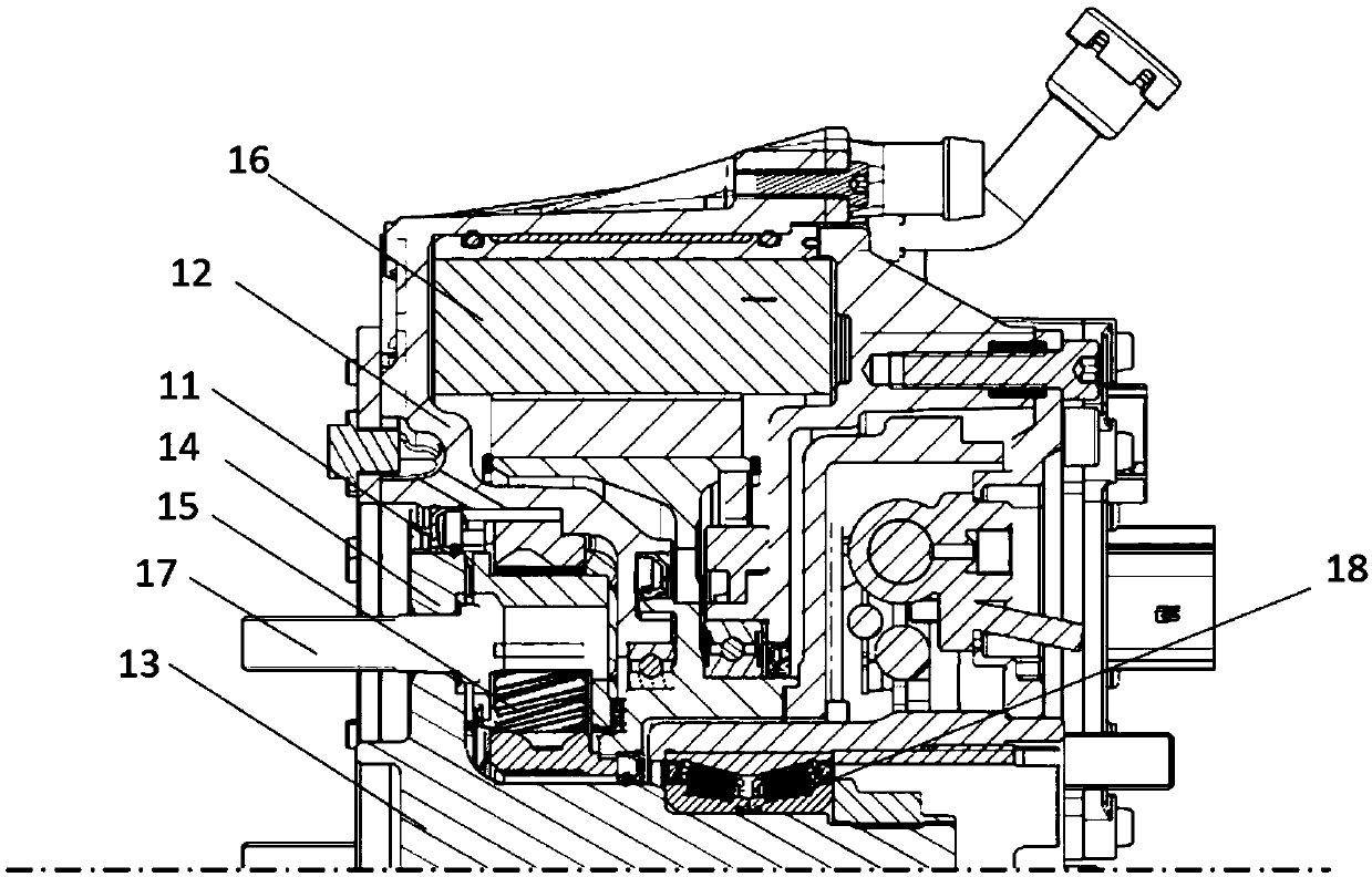
[0020] figure 1 A half-sectional view of a wheel hub drive according to the invention is shown. The wheel hub driving device includes a wheel hub (not shown) for supporting vehicle tires, a flange shaft 13, a hub bearing 18 supporting the flange shaft 13, a speed reducer 15, a motor, a motor housing 12 for holding and a seal device 11. In the motor housing 12 is mounted an electric motor with a rotor 16 , which drives a flange shaft 13 via a reduction gear 15 , and a hub bearing 18 is arranged between the flange shaft and the hub drive housing. The flange shaft 13 has a flange disc 14 at the end, and a plurality of screw rods 17 are arranged on the flange disc 14, and these screw rods 17 are evenly distributed on the circumference of the flange disc 14, and the screw rods 17 are fixedly connected with the hub, so that The flange shaft 13 is fixedly connected with the hub. When the rotor 16 of the motor rotates the flange shaft 13 through the reducer 15 made of planetary gea...


PUM


Abstract

The invention relates to a sealing device (11) and a hub driving device. The sealing device (11) is provided with an annular sealing body (3) made of an elastic material, the sealing body (3) is provided with sealing lips (7) compressed on the sealing surface, the sealing lips (7) and the sealing surface are dynamically sealed, the sealing device (11) is further provided with a reinforcing ring (6) integrally arranged with the sealing lips (7), the rigidity of the reinforcing ring (6) is larger than the rigidity of the sealing lips (7), and the hub driving device is provided with the sealing device.

Description

technical field [0001] The invention relates to a sealing device for dynamic sealing of sealing surfaces. The invention also relates to a wheel hub drive for a vehicle, which has a sealing device as described above. Background technique [0002] The traditional sealing device is mainly composed of a dust cover and a sealing body made of rubber. There is always a skeleton in the sealing body, and the sealing body has a sealing lip that forms a dynamic seal with the sealing surface for sealing lubricating oil. Additionally, the seal body has a dust lip that forms a dynamic seal with the shield to prevent contamination from entering the oil area. [0003] However, when the sealing device is used, for example, in a wheel hub driving device, since the sealing device is arranged between the housing and the flange shaft, the flange shaft has relatively large radial runout relative to the sealing device. In response to this situation, usually, the waist connecting the main body of...

Claims


Application Information

Patent Timeline
Patent Type & Authority Applications(China)
IPC IPC(8): F16H57/029F16J15/3232F16J15/3252
CPCF16H57/029F16J15/3232F16J15/3252
Inventor 刘鑫张岳林
Owner SCHAEFFLER TECH AG & CO KG
Why Eureka
Try Eureka