A wet garbage dryer
A technology of dryer and drying mechanism, applied in dryer, drying, non-progressive dryer and other directions, can solve the problems of large workload and injury of sanitation workers, optimize drying effect and reduce workload , the effect of reducing weight
- Summary
- Abstract
- Description
- Claims
- Application Information
AI Technical Summary
Problems solved by technology
Method used
Image
Examples
Embodiment 1
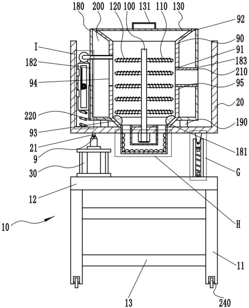
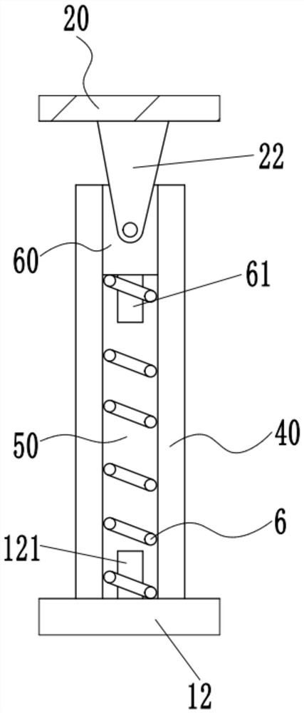
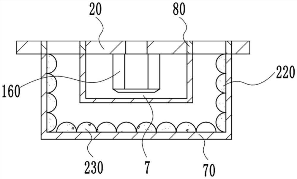
[0038] Such as figure 1 , figure 2 and image 3 As shown, a wet garbage dryer provided by the embodiment of the present invention includes a frame 10, a portal frame 20, a drying mechanism and a recovery box 70. The frame 10 includes two pairs of bottom columns 11 and is arranged on two For the support platform 12 on the bottom column 11, a pair of bottom columns 11 are connected by a pair of cross bars 13, and the bottom end of the bottom column 11 is provided with a self-locking universal wheel 240. Wheel 240, so it is convenient to move the wet garbage dryer. The two sides of the upper end of the support table 12 are respectively provided with an ejection cylinder 30 and a pair of guide plates 40, and a pair of guide plates 40 form a guide Groove 50, the outer end of the top plate of the portal frame 20 has a connecting rod 21 and a connecting plate 22, the connecting rod 21 is hinged on the extension rod of the ejection cylinder 30, specifically, the ejection cylinder ...
Embodiment 2
[0043] Such as figure 1 and Figure 4 As shown, on the basis of Embodiment 1, a drive connection mechanism is provided between the blower 140 and the inner end of the top plate of the door frame 20, and the drive connection mechanism connects the blower 140 to the door frame. The top plate of the frame 20 is connected, and the driving connection mechanism can drive the blower 140 to move, so that the wet garbage dryer can fully dry the garbage in the drying box 90, which improves the drying efficiency of the wet garbage. The drying effect of the dryer on wet garbage.
[0044] Such as Figure 4 As shown, the drive connection mechanism includes a second motor 1, a gear 2 and a die plate 3, and the second motor 1 is arranged on the mounting plate 24 located on the inner side of the side arm of the portal frame 20, so The gear 2 is sleeved on the output shaft of the second motor 1, the blower 140 is arranged on one end of the mouth plate 3, and the other end of the mouth plate ...
Embodiment 3
[0046] Such as figure 1 As shown, on the basis of the second embodiment, the outside of the drying box 90 is provided with an outer box 180, the upper end of the outer box 180 is open, and the first cone located at the upper end of the drying box 90 92 is connected to the upper end of the outer box 180, and the lower end of the outer box 180 is connected to the top plate of the portal frame 20 through a pair of support columns 190, and the middle part of the lower end of the outer box 180 is provided with a through hole 181, The second cone 93 located at the lower end of the drying box 90 is located in the through hole 181, and the second cone 93 is fixedly connected to the side wall of the through hole 181, and the outer box 180 is connected to the An annular cavity 200 is formed between the drying boxes 90, the air inlet pipe 150 is slidingly fitted with the air inlet opening 182 on one side of the outer box 180, and the air inlet pipe 150 passes through the air inlet openin...
PUM
 Abstract
Description
Claims
Application Information
 - R&D
- Intellectual Property
- Life Sciences
- Materials
- Tech Scout
- Unparalleled Data Quality
- Higher Quality Content
- 60% Fewer Hallucinations
Browse by: Latest US Patents, China's latest patents, Technical Efficacy Thesaurus, Application Domain, Technology Topic, Popular Technical Reports.
© 2025 PatSnap. All rights reserved.Legal|Privacy policy|Modern Slavery Act Transparency Statement|Sitemap|About US| Contact US: help@patsnap.com


