
Cement product forming mold

A technology for forming molds and cement products, applied in the directions of molds, forming indenters, manufacturing tools, etc., can solve the problems of small application scope, inability to control the size of grid gaps, affecting the service life of cement manhole covers, etc. quality effect

Active Publication Date: 2020-01-03
西藏藏建科技股份有限公司
View PDF7 Cites 7 Cited by
  • Summary
  • Abstract
  • Description
  • Claims
  • Application Information

AI Technical Summary

Problems solved by technology

[0003] However, the molds of the existing grid structure cement manhole covers have the following problems in the process of use. a. Traditional molds cannot control the size of the grid gap during the production process. When making grid cement manhole covers of different specifications, it is necessary to select the corresponding mold. , the scope of application is small
b. The slurry is directly injected into the mold during the use of the traditional mold, which cannot guarantee the density of the slurry inside the mold, resulting in gaps inside the formed cement manhole cover, which affects the service life of the cement manhole cover
[0004] For the technical problems existing in the use of molds for making cement products at present, personnel in related technical fields have conducted research and made adaptation improvements. For example, the Chinese utility model patent No. 2018210525160 is a mold for cement prefabricated products. It has the advantages of simple structure and convenient use. However, the problems existing in the use of the mold of the existing grid structure cement manhole cover mentioned above are not mentioned.

Method used


Image

  • Cement product forming mold
  • Cement product forming mold
  • Cement product forming mold

Examples


Embodiment Construction

[0026] The embodiments of the present invention will be described in detail below with reference to the accompanying drawings, but the present invention can be implemented in many different ways defined and covered by the claims.

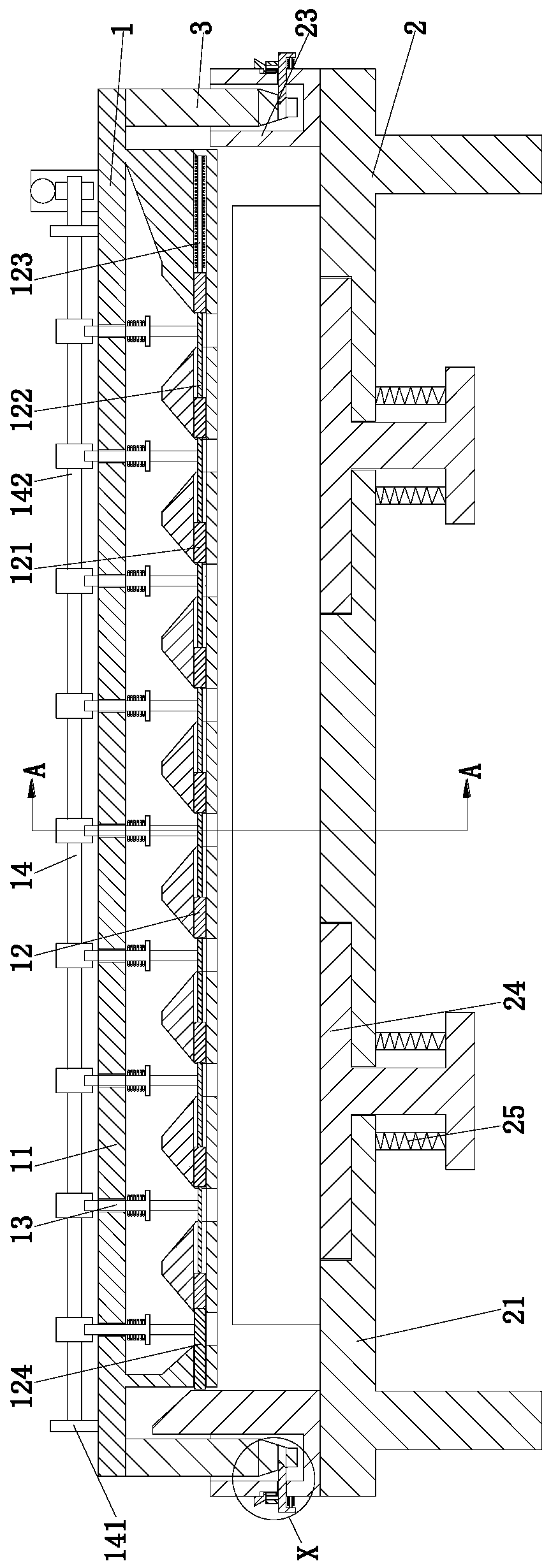
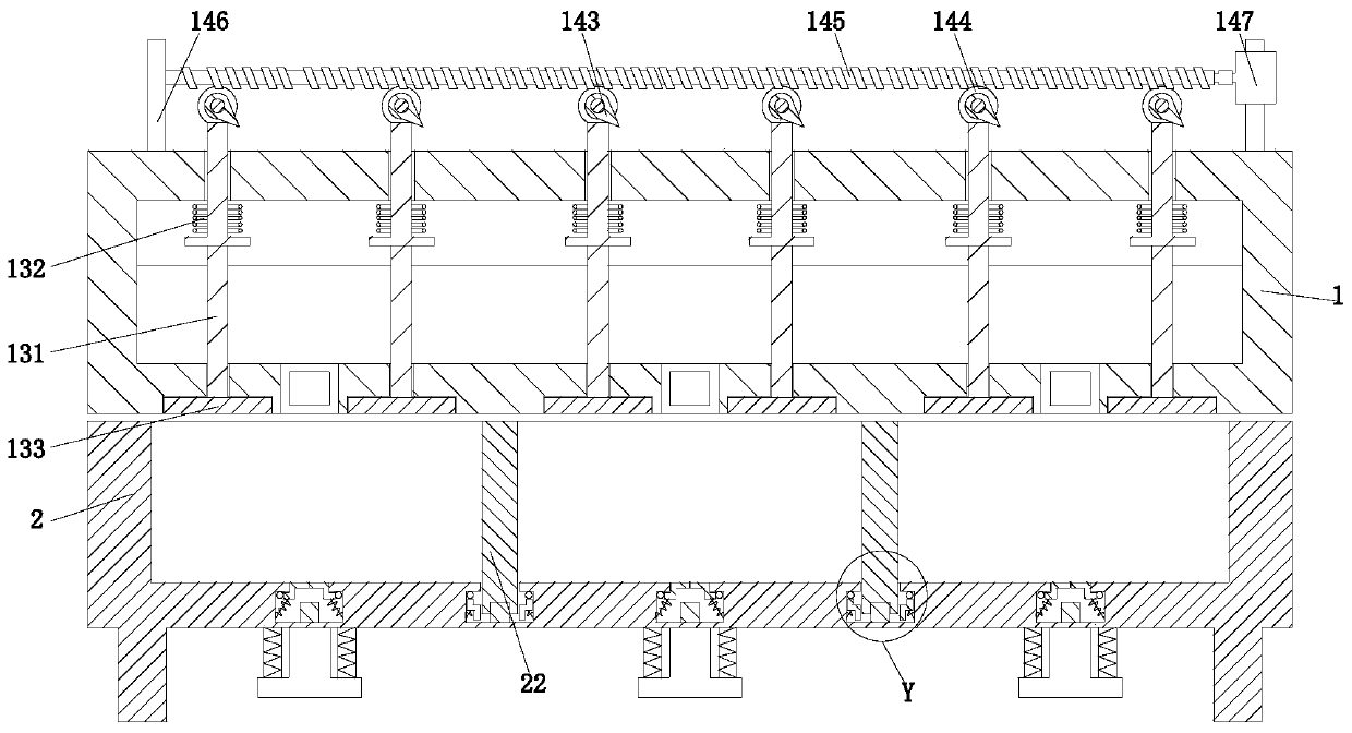
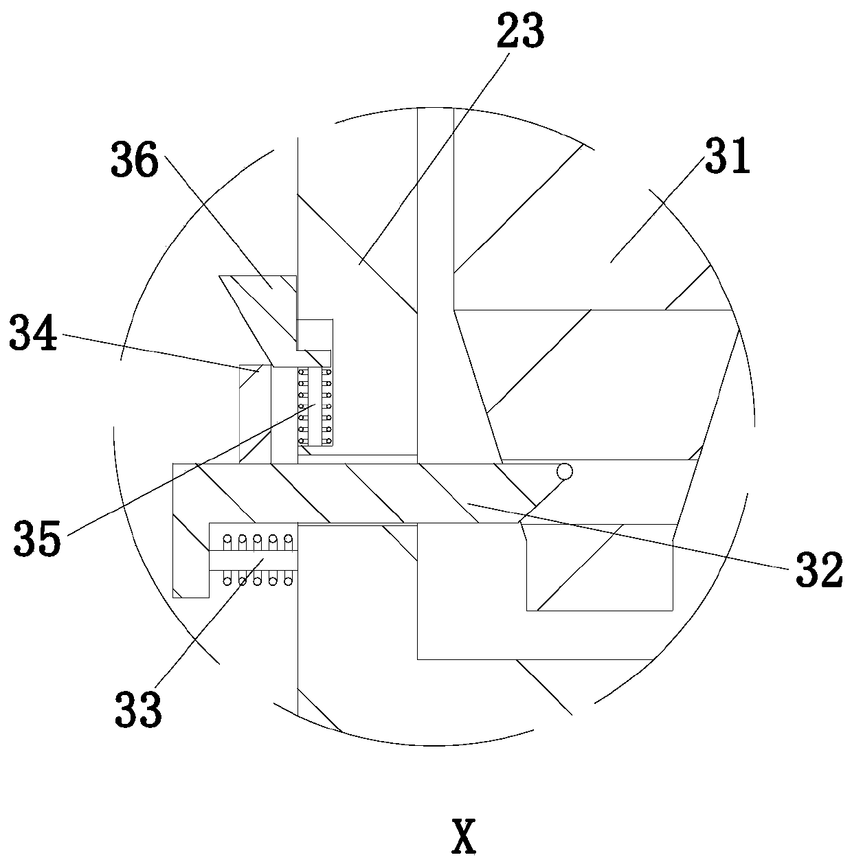
[0027] Such as Figure 1 to Figure 4 As shown, a mold for forming cement products includes an upper mold cavity 1 and a lower mold cavity 2 , and the upper mold cavity 1 is connected to the lower mold cavity 2 through a clamping mechanism 3 .

[0028] The lower mold cavity 2 includes a bearing frame 21, and the inner wall of the lower end of the bearing frame 21 is provided with blocking branch chains 22 equidistant from the front to the rear, and the front and rear sides of the bearing frame 21 are symmetrically provided with connecting grooves 23, which are located at the front end of the bearing frame 21. The inner side wall of the connection groove 23 is an inwardly inclined structure from top to bottom, and the lower end of the bearing frame 21...


PUM


Abstract

The invention relates to a cement product forming mold which comprises an upper mold cavity and a lower mold cavity. The upper mold cavity is connected to the lower mold cavity through a clamping mechanism. The cement product forming mold can solve the following problems existing in the using process of an existing mold of a cement manhole cover of a grid structure, wherein the problems comprise that as for the traditional mold, the size of a grid gap cannot be controlled in the manufacturing process, corresponding molds need to be selected when grating cement manhole covers in different specifications are manufactured, and the application range is small; and b, in the using process of the traditional mold, slurry is directly injected into the mold, the density of the slurry inside the mold cannot be guaranteed, consequently gaps exist in the formed cement manhole covers, and the service life of the cement manhole covers is influenced.

Description

technical field [0001] The invention relates to the technical field of molds, in particular to a molding mold for cement products. Background technique [0002] Cement products belong to the supporting products of building facilities. The molding process is to pour cement mortar into the mold of prefabricated cement products and extrude them. Among them, the shape and structure of the mold will determine the quality of the prefabricated cement product. The cement manhole cover with a grid-like structure mainly adopts the method of solidification and molding after pouring with a mold in the production process. [0003] However, the molds of the existing grid structure cement manhole covers have the following problems in the process of use. a. Traditional molds cannot control the size of the grid gap during the production process. When making grid cement manhole covers of different specifications, it is necessary to select the corresponding mold. , the scope of application is...

Claims


Application Information

Patent Timeline
Patent Type & Authority Applications(China)
IPC IPC(8): B28B3/02B28B3/08B28B7/00B28B7/18B28B13/02B28B13/06
CPCB28B3/022B28B3/083B28B7/0091B28B7/186B28B13/0215B28B13/067
Inventor 刘金江张国华
Owner 西藏藏建科技股份有限公司
Learn More