
A universal ball mesh belt and its production process

A universal ball, production process technology, applied in the directions of transportation, packaging, conveyors, etc., can solve the problems of difficult sorting and rotation of the same machine, difficult to meet the actual use requirements, etc., and achieve the effect of wide applicability

Active Publication Date: 2022-07-01
南通拓新自动化设备科技有限公司
View PDF12 Cites 0 Cited by
  • Summary
  • Abstract
  • Description
  • Claims
  • Application Information

AI Technical Summary

Problems solved by technology

[0004] However, the top wall of the module body in the prior art is a single plane, and the material and the module body are relatively static during the conveying process, so the material can only move at a uniform speed in a single direction under the action of its driving mechanism, and it is difficult to move on the same machine. It is difficult to realize the functions of accelerating forward, reversing, sorting and rotating, etc., so it needs to be improved

Method used


Image

  • A universal ball mesh belt and its production process
  • A universal ball mesh belt and its production process
  • A universal ball mesh belt and its production process

Examples


Embodiment 1

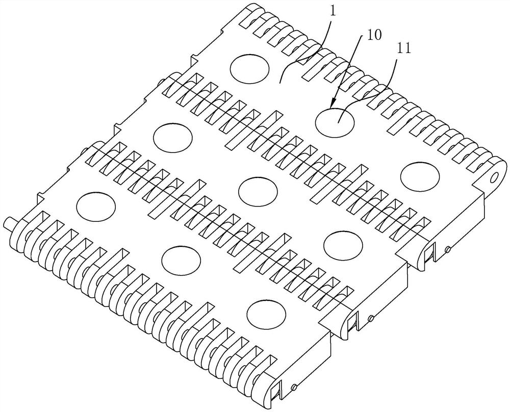
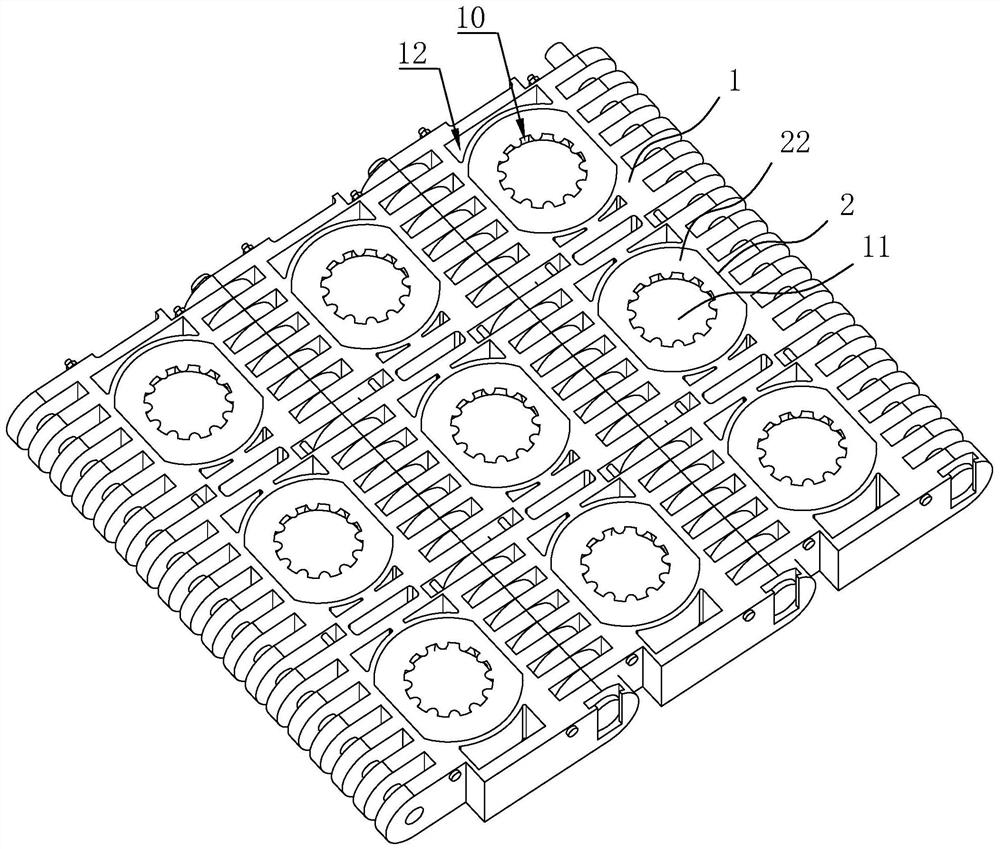
[0039] A universal ball mesh belt, refer to figure 1, which includes a number of module bodies 1 that are rotatably connected by pins. A plurality of accommodating cavities 10 are arranged in the plurality of module bodies 1 along the length direction thereof, and balls 11 are arranged in each of the plurality of accommodating cavities 10 .

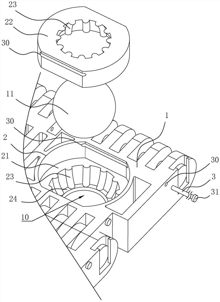
[0040] refer to figure 1 and figure 2 , the plurality of accommodating cavities 10 are open at both ends, the two ends of the plurality of balls 11 respectively protrude from the openings at both ends of the corresponding accommodating cavities 10, and the inner diameters of the openings at both ends of the plurality of accommodating cavities 10 are smaller than the inner diameter of the middle The diameter of the several balls 11 is larger than the diameter of the inner edge of the openings at both ends of the corresponding accommodating cavity 10 , and the several balls 11 are clearance-fitted with the corresponding accommodating cav...

Embodiment 2

[0048] A production process based on a universal ball mesh belt, comprising the following steps:

[0049] S1. The module body 1, the balls 11 and the lower limit convex ring 22 of corresponding specifications are produced by an injection mold.

[0050] S2. First place the balls 11 in the accommodating holes 2 of the module body, and then insert the lower limit convex ring 22 into the corresponding accommodating holes 2 to cover the balls 11, after which the balls 11 can be placed in the upper limit convex ring 21 and the accommodating cavity 10 enclosed by the lower limit convex ring 22 can rotate freely.

[0051] S3. The connection between the lower limit convex ring 22 and the accommodating hole 2 is welded by the ultrasonic plastic welding machine, so that the lower limit convex ring 22 is firmly connected with the accommodating hole 2, and it is naturally cooled, and then several module bodies 1 are passed through the pin shaft. connected to complete the production of the...


PUM


Abstract

The invention discloses a universal ball mesh belt and a production process thereof, relates to the technical field of conveying mesh belts, and aims to solve the technical problem that the existing module body can only carry out linear and single-direction uniform conveying. The technical solution points are several module bodies There are several accommodating cavities along the length direction of the several accommodating cavities. Both ends of the several accommodating cavities are open. There are balls, some of which are matched with the corresponding accommodating cavity, the diameters of some of the balls are larger than the diameter of the inner edge of the openings at both ends of the corresponding accommodating cavity, and the two ends of the plurality of balls protrude from the openings at both ends of the corresponding accommodating cavity. During the conveying process of the universal ball mesh belt, the balls can be used to control the material conveyed outside the universal ball mesh belt, so as to realize the relative movement between the material and the module body, so as to realize the accelerated advance, reverse, and separation of the material. Functions such as picking and rotation have wider applicability.

Description

technical field [0001] The invention relates to the technical field of conveyor mesh belts, and more particularly, to a universal ball mesh belt and a production process thereof. Background technique [0002] A mesh belt is a mechanical element that drives material conveyance through friction. [0003] The existing Chinese patent with the authorization announcement number CN205633877U provides a modular mesh belt, which includes a module body and connecting teeth, each connecting tooth is provided with a pin hole in parallel position, and the two module bodies pass through in sequence. Placed, the connecting teeth can be closely meshed, the pin holes can be overlapped, the pin holes are pierced with pins, and the two sides of the pin holes are blocked with plugs to realize the connection of the two module bodies; according to the order of this method After installation, a conveyor belt with parallel sides and a flat surface can be formed between the module bodies. [0004]...

Claims


Application Information

Patent Timeline
Patent Type & Authority Patents(China)
IPC IPC(8): B65G15/30B65G15/52
CPCB65G15/30B65G15/52B65G17/08B65G17/32B65G17/40
Inventor 曹明鑫
Owner 南通拓新自动化设备科技有限公司
Learn More