Architectural energy-saving composite wall connecting bridge

A composite wall and building energy-saving technology, applied in buildings, building components, building structures, etc., can solve the problems of forgetting to place connecting bridges, poor connection stability, prolonging construction time, etc. The effect of facilitating production and reducing production costs

Active Publication Date: 2020-01-03
HENAN POLYTECHNIC
View PDF7 Cites 7 Cited by
  • Summary
  • Abstract
  • Description
  • Claims
  • Application Information

AI Technical Summary

Problems solved by technology

[0003] High rate, EPS insulation board and combined steel formwork are often used to form an air composite wall, and then concrete is poured into the hollow composite wall. After the concrete is formed, the combined steel formwork is removed, and the concrete and insulation board are connected by a connecting bridge to form an insulation wall. Existing The connection bridges are usually put in when the insulation boards are spliced. When the insulation boards are spliced, there are often omissions. If you forget to put the connection bridges, disassemble the spliced ​​insulation boards and then put them into the connection bridges. Repeated disassembly of the insulation boards will affect the splicing of the insulation boards. At the same time, the construction time is prolonged. Although the existing free connection bridge can be installed after the insulation board is spliced, the connection stability between the free connection bridge and the insulation board is poor, and only the free connection bridge can be connected to the insulation board. , it is impossible to form an effective connection between the insulation board and the combined steel formwork, and the operation is cumbersome, which cannot meet the actual needs, so we invented an energy-saving composite wall connection bridge

Method used


Image

  • Architectural energy-saving composite wall connecting bridge
  • Architectural energy-saving composite wall connecting bridge
  • Architectural energy-saving composite wall connecting bridge

Examples


Embodiment Construction

[0015] In order to make the purpose, technical solutions and advantages of the embodiments of the present invention clearer, the technical solutions in the embodiments of the present invention will be clearly and completely described below in conjunction with the drawings in the embodiments of the present invention. Obviously, the described embodiments It is a part of embodiments of the present invention, but not all embodiments. Based on the embodiments of the present invention, all other embodiments obtained by persons of ordinary skill in the art without creative efforts fall within the protection scope of the present invention.

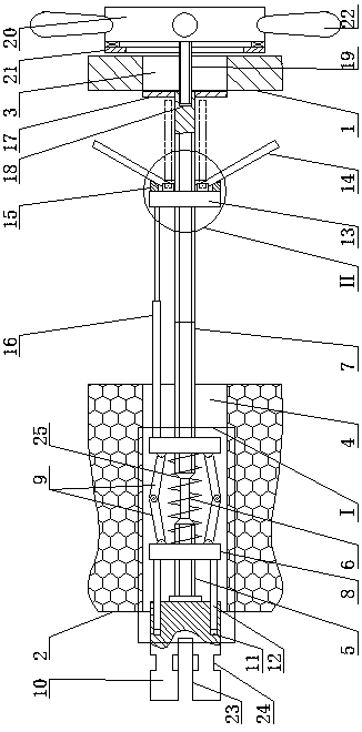
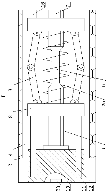
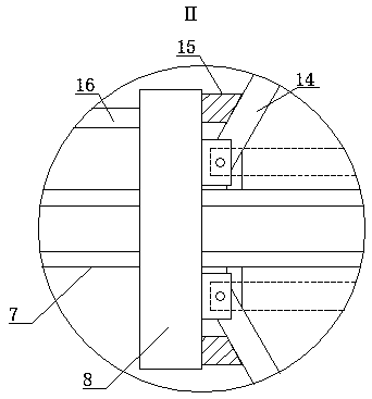
[0016] The building energy-saving composite wall connecting bridge, as shown in the figure, includes a combined steel formwork 1, the left side of the combined steel formwork 1 is provided with an insulation board 2, the right side of the combined steel formwork 1 is provided with a reserved hole 3, and the left side On the side, a through hole 4 ...


PUM


Abstract

Provided is an architectural energy-saving composite wall connecting bridge. The architectural energy-saving composite wall connecting bridge comprises a combined steel formwork, the left side of thecombined steel formwork is provided with an insulation board, a preformed hole is formed in the right side of the combined steel formwork, a through hole collinear with the central line of the preformed hole is formed in the left side of the insulation board through hot melting, a short screw coaxial with the through hole is arranged on the left portion of the through hole, the right end of the short screw is fixedly connected with the left end of a connecting rod coaxial with the short screw, and the right end of the connecting rod is fixedly connected with the left end of a long screw coaxial with the connecting rod. The helical directions of threads at the two ends of the long screw are opposite, and the helical direction of a thread of the short screw is opposite to that of the threadat the left end of the long screw. The bridge is simple in structure, convenient to use and operate and suitable for connection of the insulation boards and the combined steel formworks which are assembled respectively, the situation that the connecting bridge is missed to be placed on the insulation boards, the insulation boards which have been assembled need to be removed is avoided, clamping force to the insulation boards and clamping force to the combined steel formworks are formed separately, and therefore, backside or opposite offset between the insulation boards and combined steel formworks is avoided.

Description

technical field [0001] The invention belongs to the field of building wall structure connectors, in particular to a building energy-saving composite wall connecting bridge. Background technique [0002] In order to improve the energy-saving and thermal insulation effect of buildings, prolong the service life of building components and improve the construction efficiency of buildings [0003] High rate, EPS insulation board and combined steel formwork are often used to form an air composite wall, and then concrete is poured into the hollow composite wall. After the concrete is formed, the combined steel formwork is removed, and the concrete and insulation board are connected by a connecting bridge to form an insulation wall. Existing The connection bridges are usually put in when the insulation boards are spliced. When the insulation boards are spliced, there are often omissions. If you forget to put the connection bridges, disassemble the spliced ​​insulation boards and then...

Claims


Application Information

Patent Timeline
Patent Type & Authority Applications(China)
IPC IPC(8): E04B1/76E04G17/00E04G17/06
CPCE04B1/7629E04G17/001E04G17/06Y02A30/00Y02B30/90
Inventor 宋丽红樊松丽马臻臻
Owner HENAN POLYTECHNIC
Why Eureka
Try Eureka