
Emergency opening method of fire door

A fire door and door body technology, applied in fire doors, door/window accessories, wing fan openers, etc., can solve the problems of inconvenient escape of people behind, hindering the delay of fire and the spread of smoke, etc.

Active Publication Date: 2020-01-03
ZHEJIANG ZHENGXIAO FIREPROOF DOOR & WINDOW CO LTD
View PDF8 Cites 6 Cited by
  • Summary
  • Abstract
  • Description
  • Claims
  • Application Information

AI Technical Summary

Problems solved by technology

[0002] The function of fire doors is to prevent and delay the spread of fire and smoke to the front room of fire elevators and stairs when a fire occurs, and to give pedestrians and firefighters time to evacuate or fight. At present, ordinary fire doors are basically equipped with door closers. Normally closed has no effect, it just separates the common front room of the fire elevator and stairs, but when a fire breaks out and people need to escape from the stairway, once the person in front pushes the fire door and lets go, the door closer will return to fire protection. The door is automatically closed, which brings great inconvenience to the escape of the people behind. Therefore, it is necessary for the present invention to provide a device that keeps the fire door open after being pushed open. The fire door is closed, even if the fire door is pushed open, it will always remain open. In the event of a fire, only the first person needs to push the fire door, and the subsequent evacuees can quickly pass through, and the escape efficiency is higher

Method used


Image

  • Emergency opening method of fire door
  • Emergency opening method of fire door
  • Emergency opening method of fire door

Examples


Embodiment Construction

[0062] The emergency opening method of a fire door comprises the following steps:

[0063] (1) The fire door opening stage;

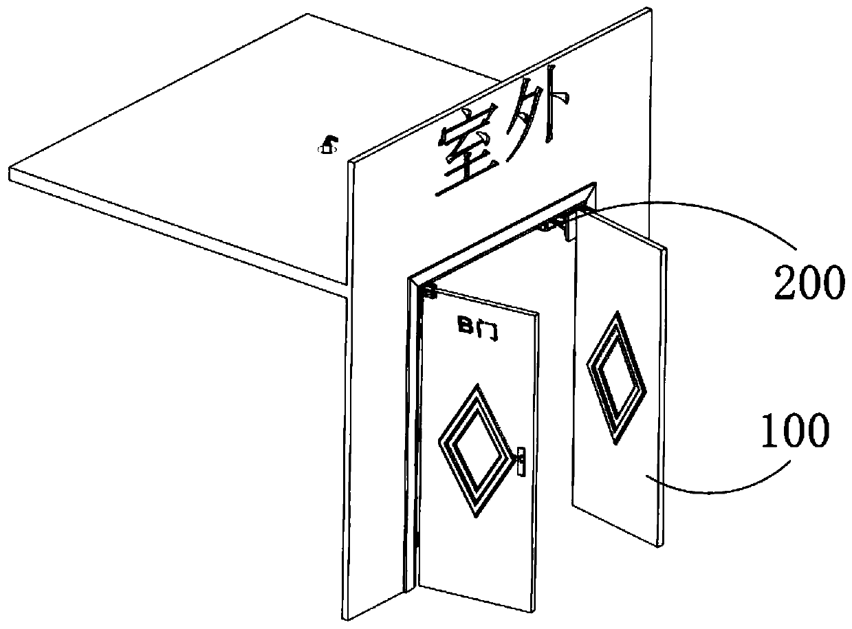
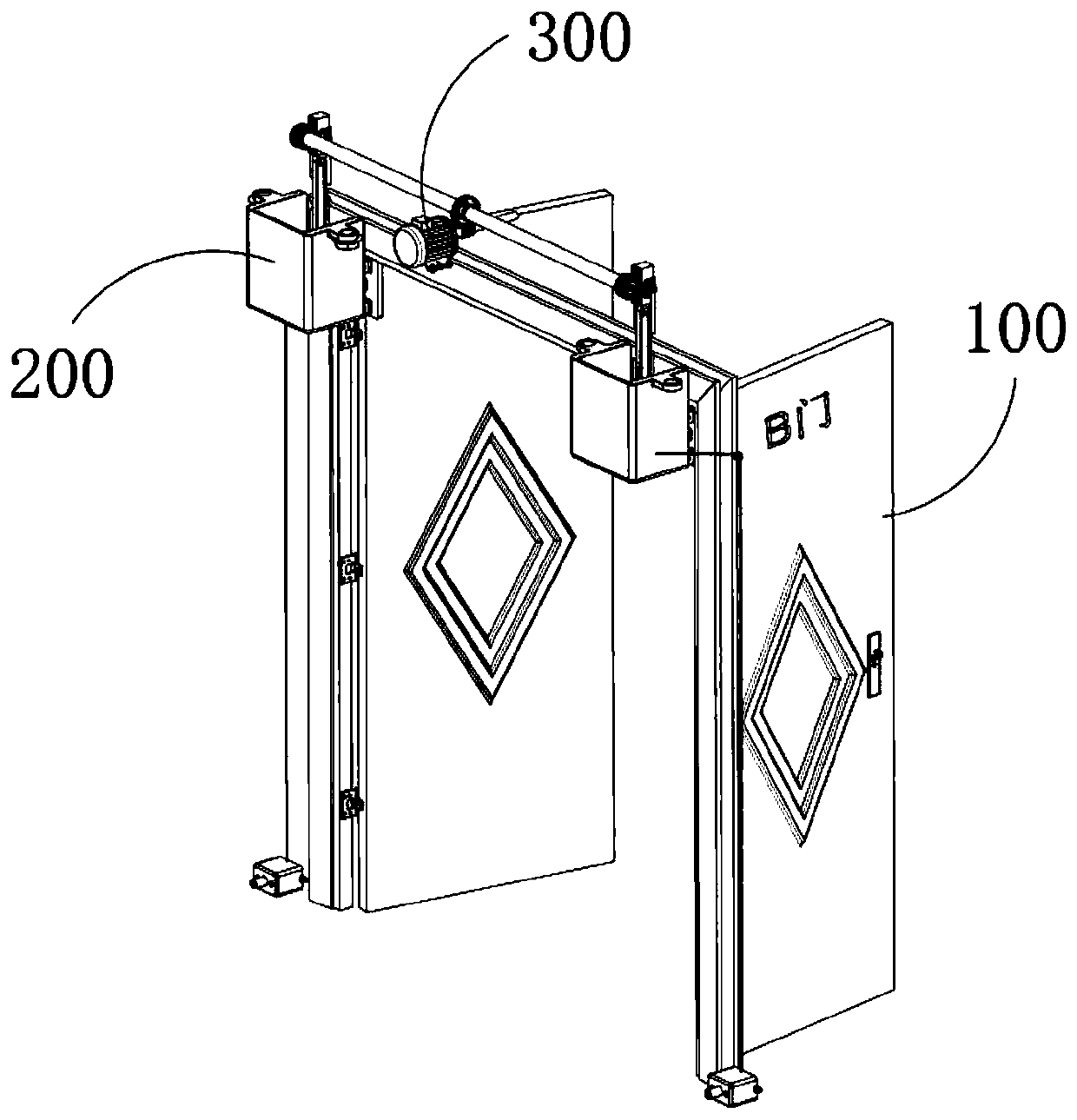
[0064] S1: When a fire breaks out, people push open the fire door body 100, and at the same time the fire door normally open device 200 is triggered to run;

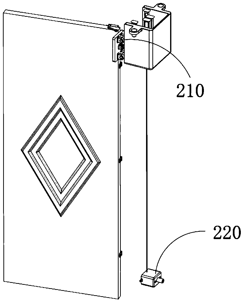
[0065] The fire door normally open device 200 is provided with two groups and corresponds to the two door panels of the fire door body 100 respectively. The fire door normally open device 200 includes a limit normally open mechanism 210, a reset close mechanism 220, and a limit normally open mechanism 220. The mechanism 210 is installed on the indoor ceiling and it is close to the hinge between the fire door body 100 and the door frame. The limit normally open mechanism 210 includes a casing, a fixed bracket 2110, a control member 2120, and a push member 2130. The casing is A rectangular shell structure with one end open and one end closed, the shell is fixedly installed on the ceiling with its o...


PUM


Abstract

The invention discloses an emergency opening method of a fire door. The emergency opening method of the fire door comprises the steps that when a fire happens, abutting push parts can drive abutting push plates to be closely attached to a fire door body all the time in the process that the fire door body is pushed by a worker to be in an open state, after the fire door body is opened, the upper end faces of limiting blocks serve as limiting planes, the free ends of triggering parts are located on the limiting planes, and therefore the abutting push plates are limited to conduct the retreat movement which is characterized in that the abutting push plates are far away from a stairway, and the fire door body can be continuously kept in an open state; and after the fire is extinguished, the worker kicks reset closing mechanisms with feet and enables two control parts to conduct the movement which is characterized in that the control parts are far away from each other, the free ends of thetriggering parts can be separated from the limiting planes of the limiting blocks, a door closer can automatically close the fire door body, an auxiliary device can apply the perpendicularly downwardacting force to connecting rods in the door closing process, the acting force enables the abutting push plates to conduct the movement consistent to the closing movement of the fire door body, and abutting push components do not affect the automatic closing operation of the fire door body.

Description

technical field [0001] The invention relates to the field of fire protection, in particular to a method for keeping a fire door normally open after being pushed open. Background technique [0002] The function of fire doors is to prevent and delay the spread of fire and smoke to the front room of fire elevators and stairs when a fire occurs, and to give pedestrians and firefighters time to evacuate or fight. At present, ordinary fire doors are basically equipped with door closers. Normally closed has no effect, it just separates the common front room of the fire elevator and stairs, but when a fire breaks out and people need to escape from the stairway, once the person in front pushes the fire door and lets go, the door closer will return to fire protection. The door is automatically closed, which brings great inconvenience to the escape of the people behind. Therefore, it is necessary for the present invention to provide a device that keeps the fire door open after being pu...

Claims


Application Information

Patent Timeline
IPC IPC(8): E05C17/02E05F1/10E06B5/16
CPCE05C17/02E05F1/10E06B5/16
Inventor 陆中艳
Owner ZHEJIANG ZHENGXIAO FIREPROOF DOOR & WINDOW CO LTD
Learn More