
Speed reducer assembly no-load moment testboard

A technology of reducer and no-load force, applied in the field of no-load torque test equipment of reducer assembly, can solve the problem that the no-load torque of reducer assembly is inconvenient to fix, affects the accuracy of fixation, angle encoder and motor cannot move, etc. problems, to facilitate the no-load torque test, improve the convenience of fixing, and improve the effect of locking force

Pending Publication Date: 2020-01-03
RES INST OF ZHEJIANG UNIV TAIZHOU
View PDF0 Cites 0 Cited by
  • Summary
  • Abstract
  • Description
  • Claims
  • Application Information

AI Technical Summary

Problems solved by technology

[0002] In the existing technology center, the existing no-load moment test bench of the reducer assembly is inconvenient to fix when measuring the no-load moment of the reducer assembly, and the clamping and fixing effect is not good, which affects the authenticity of the measurement data, and The angle encoder and motor cannot move, affecting the accuracy of the fixation
[0003] In the past, the no-load torque test process of the reducer assembly was complicated, and the test effect was not good. Now there is an urgent need for a reducer assembly no-load torque test bench to solve the above problems

Method used


Image

  • Speed reducer assembly no-load moment testboard
  • Speed reducer assembly no-load moment testboard
  • Speed reducer assembly no-load moment testboard

Examples


specific Embodiment approach

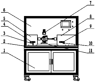
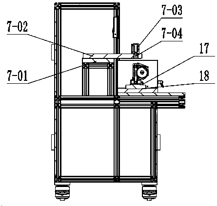
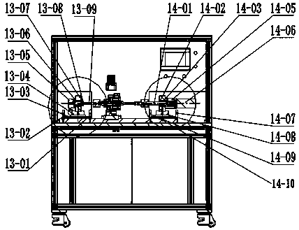
[0028] Specific implementation method: first, the reducer assembly 16 is fixed on the upper end surface of the positioning member 18 through the fixed pin 17, and the lower pressure cylinder 704 is pressed against the upper end surface of the reducer assembly 16 by the lower pressure cylinder 703, because the support plate 701 and The cylinder mounting plate 702 makes the support of the downward pressure cylinder 703 more stable.

[0029] The reducer assembly 16 is connected with the left transfer shaft 1309 through the left coupling 12, because the left bracket 1307 and the lock nut 1308 are installed, the left transfer shaft 1309 has better support stability, because the first The bearing 1306 makes the left transfer shaft 1309 more stable when rotating. At this time, the operator adjusts the front and rear positions of the transfer board 1304 by twisting the wrench 3 with his left hand. Because the first line rail 1303 is installed on the lower end of the transfer board 1304...


PUM


Abstract

The invention provides a speed reducer assembly no-load moment testboard, which comprises a supporting plate, a cylinder mounting plate and a downward pressing cylinder, wherein the supporting plate is mounted on the rear side of a speed reducer assembly; the cylinder mounting plate is mounted on the upper end surface of the supporting plate; and the downward pressing cylinder is mounted on the front side of the upper end surface of the cylinder mounting plate. The speed reducer assembly no-load moment testboard further comprises a locking nut and a left coupling shaft, wherein the left end surface of a left coupler is connected with a left coupling shaft, the locking nut is installed on the annular side surface of the left coupling shaft, a left bracket is installed on the annular side surface of the left coupling shaft, the left end surface of the left bracket is connected with an angle encoder, and a linear rail is installed on the lower end surface of the left bracket. The speed reducer assembly no-load moment testboard solves the problem that the fixing precision is influenced because the angle encoder cannot be moved and adjusted when a speed reducer is tested.

Description

technical field [0001] The invention relates to a no-load moment test bench for a reducer assembly, which belongs to the field of no-load moment test equipment for a reducer assembly. Background technique [0002] In the existing technology center, the existing no-load moment test bench of the reducer assembly is inconvenient to fix when measuring the no-load moment of the reducer assembly, and the clamping and fixing effect is not good, which affects the authenticity of the measurement data, and The angle encoder and motor cannot move, affecting the accuracy of the fixation. [0003] In the past, the test process of the no-load torque of the reducer assembly was complicated, and the test effect was not good. Now there is an urgent need for a test bench of the no-load torque of the reducer assembly to solve the above-mentioned problems. Contents of the invention [0004] In view of the deficiencies in the prior art, the purpose of the present invention is to provide a no-...

Claims


Application Information

Patent Timeline
IPC IPC(8): G01M13/025G01L5/00B25B11/00
CPCB25B11/00G01L5/0061G01M13/025
Inventor 葛正杨利利王维镝李广平吴日远陈俊廷王维锐
Owner RES INST OF ZHEJIANG UNIV TAIZHOU
Learn More