

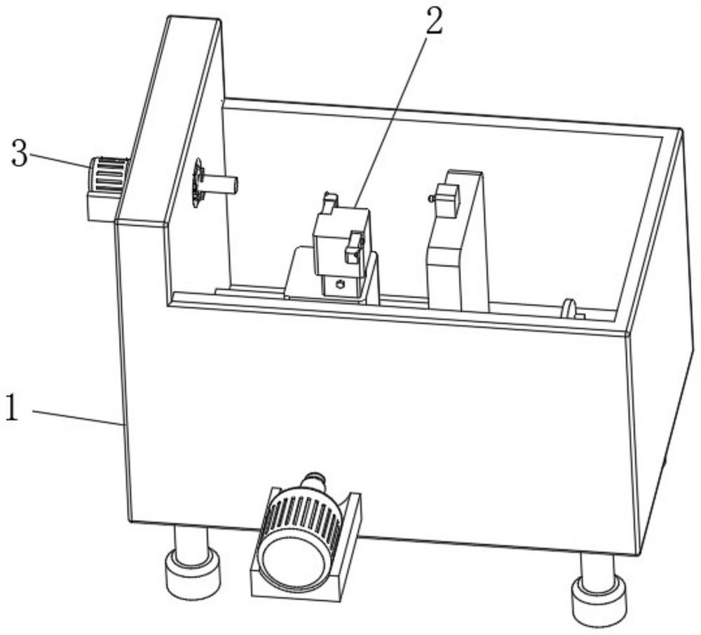
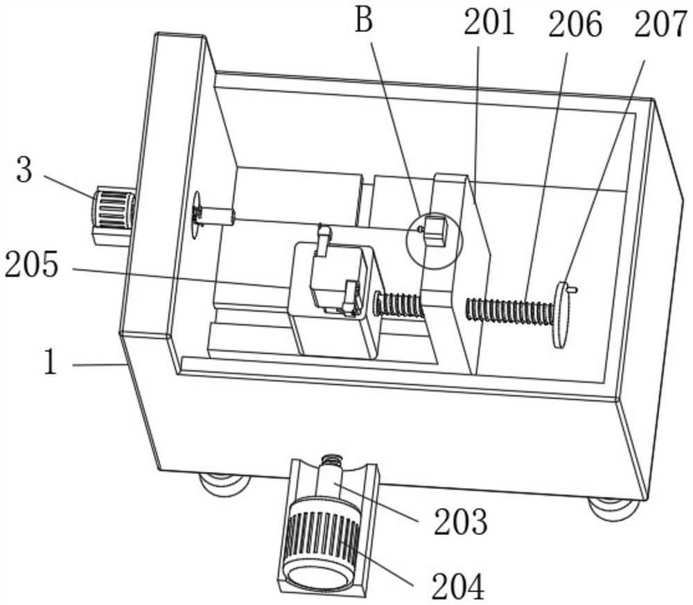
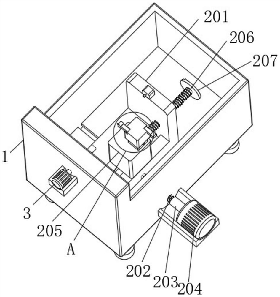
Metal cutting machine tool with automatic tool wear compensation device
An automatic compensation and metal cutting technology, which is applied in the direction of automatic control devices, metal processing machinery parts, metal processing, etc., can solve the problems of inaccurate tool compensation, cumbersome and laborious operation, and excessive compensation, so as to improve the convenience of fixing and shorten the cutting time. Improvement of processing time and processing quality
- Summary
- Abstract
- Description
- Claims
- Application Information
AI Technical Summary
Problems solved by technology
Method used
Image

Examples
Embodiment Construction
[0027] The technical solutions in the embodiments of the present invention will be clearly and completely described below in conjunction with the embodiments of the present invention. Apparently, the described embodiments are only some of the embodiments of the present invention, not all of them.
[0028] In describing the present invention, it should be understood that the terms "upper", "lower", "front", "rear", "left", "right", "top", "bottom", "inner", " The orientation or positional relationship indicated by "outside" and so on is the relative relationship of orientation or position, which is only for the convenience of describing the present invention and simplifying the description, rather than indicating or implying that the device or element referred to must have a specific orientation, or in a specific orientation. construction and operation, therefore, should not be construed as limiting the invention.
[0029] see Figure 1-8 , an embodiment provided by the presen...
PUM
 Abstract
Description
Claims
Application Information