Grid-connected inverter mains impedance detection method and power factor correction method and device

An inverter and electrical impedance technology, which is applied in the control field of photovoltaic inverters, can solve the problems of poor power factor and quality of grid-connected power

Active Publication Date: 2019-01-04
爱士惟科技股份有限公司
View PDF6 Cites 0 Cited by
  • Summary
  • Abstract
  • Description
  • Claims
  • Application Information

AI Technical Summary

Problems solved by technology

[0003] In order to solve the problem of poor power factor quality of grid-connected electric energy, the present invention proposes a grid-connected inverter market impedance detection method and a power factor correction method and device to compensate the reactive control current in real time

Method used


Image

  • Grid-connected inverter mains impedance detection method and power factor correction method and device
  • Grid-connected inverter mains impedance detection method and power factor correction method and device
  • Grid-connected inverter mains impedance detection method and power factor correction method and device

Examples


Embodiment 1

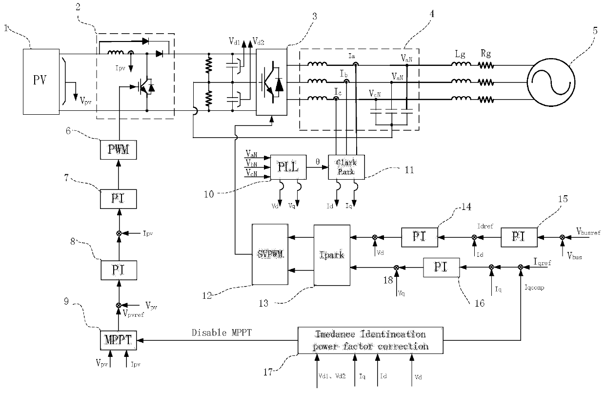
[0171] The control block diagram of the grid-connected inverter mains impedance of the embodiment of the present invention is as follows figure 1 As shown, inverters of other topologies are also applicable. The impedance detection method of the embodiment of the present invention needs active current (ie figure 1 Idref) disturbance and reactive current (ie figure 1 Iqref) disturbance in , where the active current disturbance utilizes the PV voltage on the DC control side (ie figure 1 Vpvref) in the reference disturbance is generated, and the reactive current disturbance adopts the reactive current (ie figure 1 Iqref) in the reference disturbance, the schematic diagram of the reference disturbance is as follows Image 6 As shown, among them, Vpvref_d is the PV voltage disturbance signal, which is superimposed on the voltage reference value; Iqref_d is the reactive current disturbance signal, which is superimposed on the reactive current reference value; where the wave arrow ...


PUM


Abstract

The application provides a grid-connected inverter commercial power impedance detection method and a power factor correction method and device, and relates to a control method of a photovoltaic inverter. The grid-connected inverter commercial power impedance detection method comprises the steps of setting a DC bus voltage V<bus> at the maximum voltage of the input allowance of a photovoltaic array PV, and forbidding the output voltage disturbance of a maximum power tracking unit MPPT; obtaining the inverter current and output voltage values at an active current disturbance steady state and a reactive current disturbance steady state separately; calculating the commercial power impedance according to the inverter current and output voltage values; obtaining a reactive current compensation value; superposing the reactive current compensation value on a reactive current, and obtaining the difference with a feedback reactive current and then inputting a proportional-integral regulator PI of a reactive current loop. For the commercial power terminal power factor control compensation on the commercial power impedance condition, and by the relationships of the estimated value of the detected impedance and the power factors, and the active and reactive currents and the output voltage, a reactive control current is compensated real-timely.

Description

technical field [0001] The invention relates to a control method of a photovoltaic inverter, in particular to a grid-connected inverter commercial impedance detection method and a power factor correction method and device. Background technique [0002] With the depletion of fossil energy and the increasingly serious harm to the environment, solar energy has developed rapidly as a clean energy source, and the application of grid-connected inverters has become more extensive, and its stability and efficiency have become more and more popular. focus on. Photovoltaic power stations are usually built in remote areas far away from the load center and rich in sunlight, such as deserts. The photovoltaic power generation system is connected to the load through transformers and long-distance transmission lines. When the equivalent impedance of the transformer and long-distance transmission lines is large, the power grid and Weak grid characteristics, mainly manifested in problems suc...

Claims


Application Information

Patent Timeline
Patent Type & Authority Patents(China)
IPC IPC(8): G01R27/08G01R27/26H02J3/16
CPCG01R27/08G01R27/26H02J3/16Y02E40/30
Inventor 张超袁帅廖小俊舒成维
Owner 爱士惟科技股份有限公司
Why Eureka
Try Eureka