Coreless motor stator and rotor assembling device

An assembly device, stator and rotor technology, applied in the manufacture of stator/rotor body, etc., can solve the problems of inconvenient positioning and fixing, poor use effect, and affecting processing progress

Inactive Publication Date: 2021-05-18
环一军
View PDF0 Cites 0 Cited by
  • Summary
  • Abstract
  • Description
  • Claims
  • Application Information

AI Technical Summary

Problems solved by technology

[0003] In the prior art, the existing iron-core motor stator-rotor assembly device is not convenient for positioning and fixing, which affects the processing pr

Method used


Image

  • Coreless motor stator and rotor assembling device
  • Coreless motor stator and rotor assembling device
  • Coreless motor stator and rotor assembling device

Examples


Embodiment Construction

[0018] In order to make the technical means, creative features, goals and effects achieved by the present invention easy to understand, the present invention will be further described below in conjunction with specific embodiments.

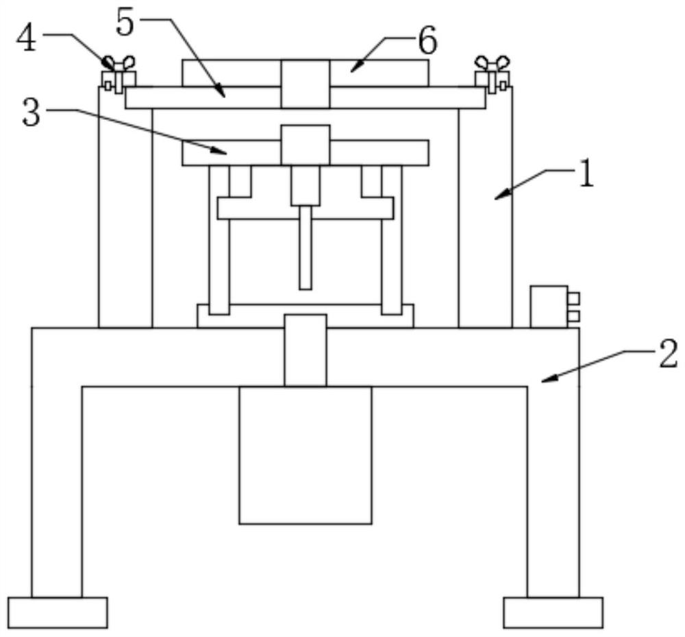
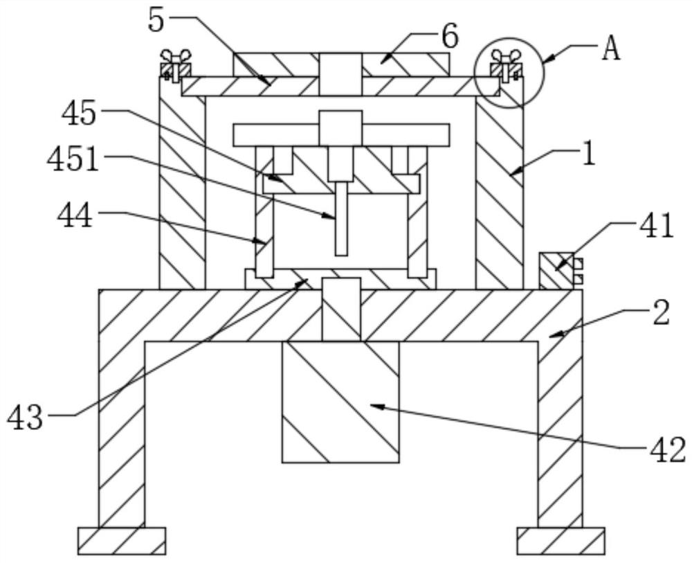
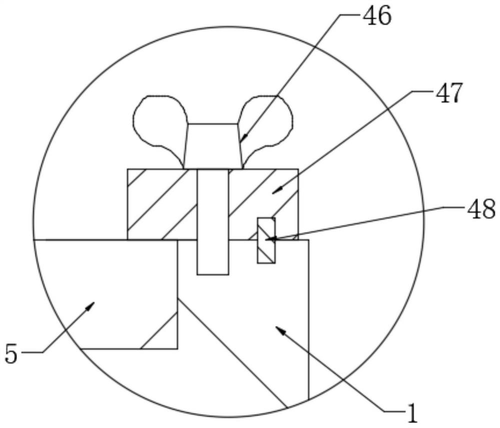
[0019] see Figure 1-Figure 3 , the present invention provides a technical solution: an iron-core motor stator and rotor assembly device, including a support plate 1, a base 2, a lower magnetic plate 4, a fixing mechanism 4, a stator 5 and an upper magnetic plate 6, and the upper end surface of the base 2 A support plate 1 is installed, a stator 5 is installed on the upper end of the support plate 1, an upper magnetic plate 6 is adsorbed on the upper end of the stator 5, a lower magnetic plate 4 is arranged on the lower side of the upper magnetic plate 6, and a magnetic plate 4 is arranged on the upper side of the base 2 for convenient Fixing mechanism4.

[0020] Facilitate that fixing mechanism 4 comprises solenoid valve 41, ejection cylinder 42...


PUM


Abstract

The invention provides a coreless motor stator and rotor assembling device which comprises a supporting plate, a base, a lower gear magnetic plate, a stator, an electromagnetic valve, an ejection air cylinder, a top plate, a fixing plate, a positioning seat, a butterfly bolt, a pressing block and a positioning pin. The supporting plate is installed on the upper end face of the base, the stator is installed on the upper end face of the supporting plate, and the lower gear magnetic plate is arranged on the lower side of the upper gear magnetic plate; and the fixing plate is assembled on the upper end face of the top plate. the positioning seat is installed in the fixing plate. The electromagnetic valve is installed on the right side of the upper end face of the base. The pressing block is installed on the upper end face of the supporting plate. The upper end face of the pressing block is connected with the butterfly bolt. According to the design, the problem that an original coreless motor stator and rotor assembling device is poor in using effect is solved, and the coreless motor stator and rotor assembling device is reasonable in structure, convenient to combine and install, convenient to fix and good in using effect.

Description

technical field [0001] The invention relates to an assembly device for a stator and rotor of an iron-core motor, which belongs to the technical field of iron-core motor processing equipment. Background technique [0002] Ironless motor is a new type of special motor representing the future development direction of the motor industry. It is divided into ironless motor and ironless generator. It adopts ironless coil, carbon brush, nonmagnetic damping and rare earth permanent magnet electric technology. , changing the structure of the traditional motor using silicon steel sheet and winding stator, combined with electronic intelligent frequency conversion technology, the efficiency of the motor system is increased to more than 95%, and the ironless motor stator and rotor assembly device is required when processing the ironless motor . [0003] In the prior art, the existing iron-core motor stator-rotor assembly device is not convenient for positioning and fixing, which affects ...

Claims


Application Information

Patent Timeline
IPC IPC(8): H02K15/02
CPCH02K15/02
Inventor 环一军
Owner 环一军
Why Eureka
Try Eureka