Outdoor garbage can convenient for compression of garbage

A trash can and outdoor technology, applied in trash cans, garbage collection, household appliances, etc., can solve problems that affect normal use, cannot compress garbage, and does not have a compression structure, so as to improve the flexibility of use, facilitate follow-up processing, and improve The effect of the separation effect

Inactive Publication Date: 2020-01-07
李素庆
View PDF0 Cites 1 Cited by
  • Summary
  • Abstract
  • Description
  • Claims
  • Application Information

AI Technical Summary

Problems solved by technology

[0002] As the name implies, an outdoor trash can refers to a tool placed outdoors for people to discard garbage. Due to the large flow of people outdoors, there is more garbage generated, so the outdoor trash can often arrives in a short time. Full load status, affecting normal use
[0003] Under the above circumstances, the most convenient way is to compress the garbage in the bucket to save space, but most of the current garbage cans do not have a corresponding compression structure, and the garbage in it cannot be easily compressed

Method used


Image

  • Outdoor garbage can convenient for compression of garbage
  • Outdoor garbage can convenient for compression of garbage
  • Outdoor garbage can convenient for compression of garbage

Examples


Embodiment 1

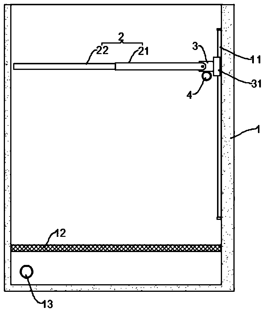
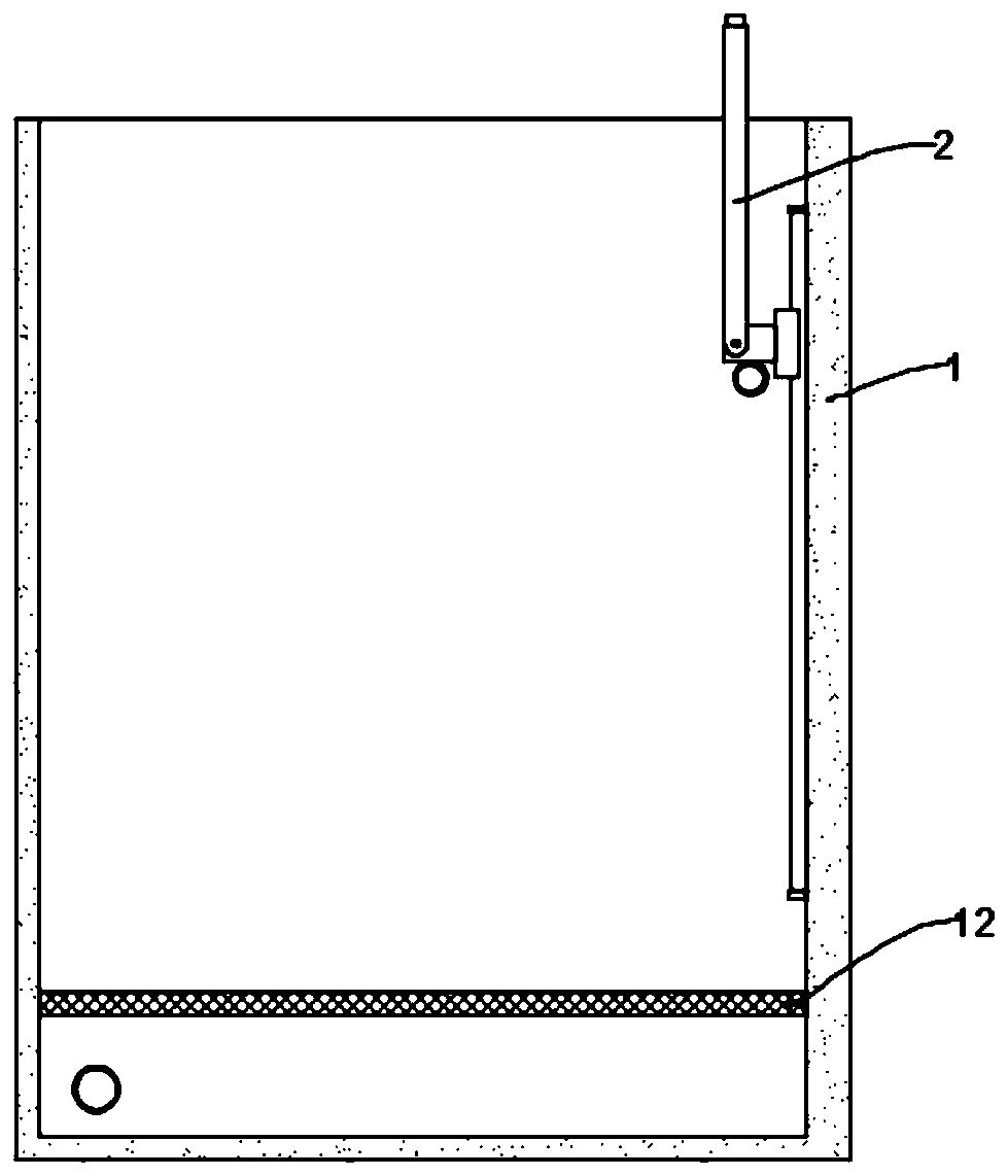
[0025] see Figure 1~2 , in an embodiment of the present invention, an outdoor trash can that is convenient for compressing garbage includes a barrel body 1; a pressing plate 2 is arranged inside the barrel body 1, and one end of the pressing plate 2 is rotatably connected to a mounting seat 3; the mounting seat 3 The inner wall of the barrel body 1 is slidably connected and can move along the vertical direction; the upper shell wall of the barrel body 1 is pierced with a limit pin 4, and the limit pin 4 and the mounting seat 3 are on the same vertical line. In the use state, the pressing plate 2 is in a vertical state, and the limit pin 4 is located under the mounting seat 3 to support the pressing plate 2. At this time, the garbage can be placed normally, and when the garbage needs to be compressed, the pressing plate 2 is turned to the horizontal state, move the limit pin 4 at the same time, and then apply a downward force to the pressure plate 2 to compress the garbage, wh...

Embodiment 2

[0033] see Figure 3-5 , the embodiment of the present invention expands other functions on the basis of embodiment 1, specifically:

[0034] A walking mechanism is installed on the side of the barrel body 1, which can facilitate the overall transfer of the outdoor trash can and improve flexibility.

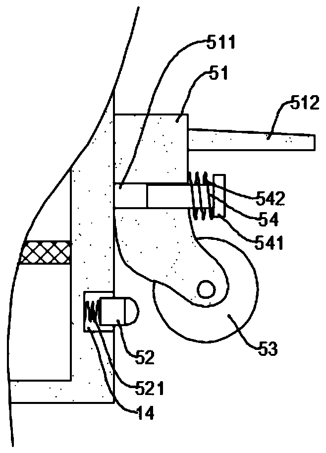
[0035] Specifically, the traveling mechanism includes a moving seat 51; the moving seat 51 is slidably connected to the outer wall of the barrel body 1 and can move along the vertical direction, the bottom of the moving seat 51 is equipped with a roller 53, and the middle part of the moving seat 51 is opened. There is a perforation 511 arranged horizontally, and a push rod 54 is pierced in the perforation 511. A connecting plate 541 is fixed at the end of the push rod 54, and a return spring 542 is connected between the connecting plate 541 and the moving seat 51; the outer wall of the barrel body 1 There is an installation groove 14 on the top, and the sliding card in the insta...


PUM


Abstract

The invention discloses an outdoor garbage can convenient for compression of garbage and relates to the field of environmental-friendly equipment. The garbage can comprises a barrel body; the barrel body is internally provided with a pressing plate; one end of the pressing plate is rotationally connected to a mounting seat; the mounting seat is slidably connected with the inner wall of the barrelbody and can move in a vertical direction; the shell wall of the upper part of the barrel body is provided with a limiting pin in a penetrating manner; and the limiting pin and the mounting seat are arranged in one vertical line. For the outdoor garbage can disclosed by the invention, by arranging the mounting seat capable of moving in the vertical direction in the barrel body and rotationally connecting the pressing plate to the mounting seat, people can conveniently compress the garbage; and meanwhile, by matching with use of the limiting pin, the pressing plate can be limited, and normal throwing of the garbage cannot be affected.

Description

technical field [0001] The invention relates to the field of environmental protection equipment, in particular to an outdoor garbage bin which is convenient for compressing garbage. Background technique [0002] As the name implies, an outdoor trash can refers to a tool placed outdoors for people to discard garbage. Due to the large flow of people outdoors, there is also more garbage generated, so the outdoor trash can often arrives in a short time. Full load status affects normal use. [0003] Under the above circumstances, the most convenient way is to compress the garbage in the bucket to save space, but most of the current garbage cans do not have a corresponding compression structure, and the garbage in the bucket cannot be compressed conveniently. Contents of the invention [0004] The object of the present invention is to provide an outdoor trash can which is convenient for compressing garbage, so as to solve the above problems. [0005] To achieve the above objec...

Claims


Application Information

Patent Timeline
Patent Type & Authority Applications(China)
IPC IPC(8): B65F1/14
CPCB65F1/1405B65F1/1468
Inventor 李素庆
Owner 李素庆
Why Eureka
Try Eureka