Forming device for linear motor stator processing and production

A technology of linear motor and forming device, used in positioning device, feeding device, storage device, etc., can solve the problems of stator blanking, affecting stamping, inconvenient for dust cleaning, etc., to achieve stable up and down movement, convenient clamping and stamping molding effect

Inactive Publication Date: 2021-08-27
深圳市森克威尔自动化有限公司
View PDF0 Cites 1 Cited by
  • Summary
  • Abstract
  • Description
  • Claims
  • Application Information

AI Technical Summary

Problems solved by technology

[0004] 1. The existing motor stator stamping and forming device, after the stamping is completed, release the switch, the stamping head rises, and then take out the finished product by hand, which will cause safety hazards, and it is inconvenient to unload the stamped stator;
[0005] 2. The existing device is inconvenient to collect the stamped stator, and it is inconvenient to clean the dust generated by stamping, which affects the stamping process

Method used


Image

  • Forming device for linear motor stator processing and production
  • Forming device for linear motor stator processing and production
  • Forming device for linear motor stator processing and production

Examples


Embodiment 1

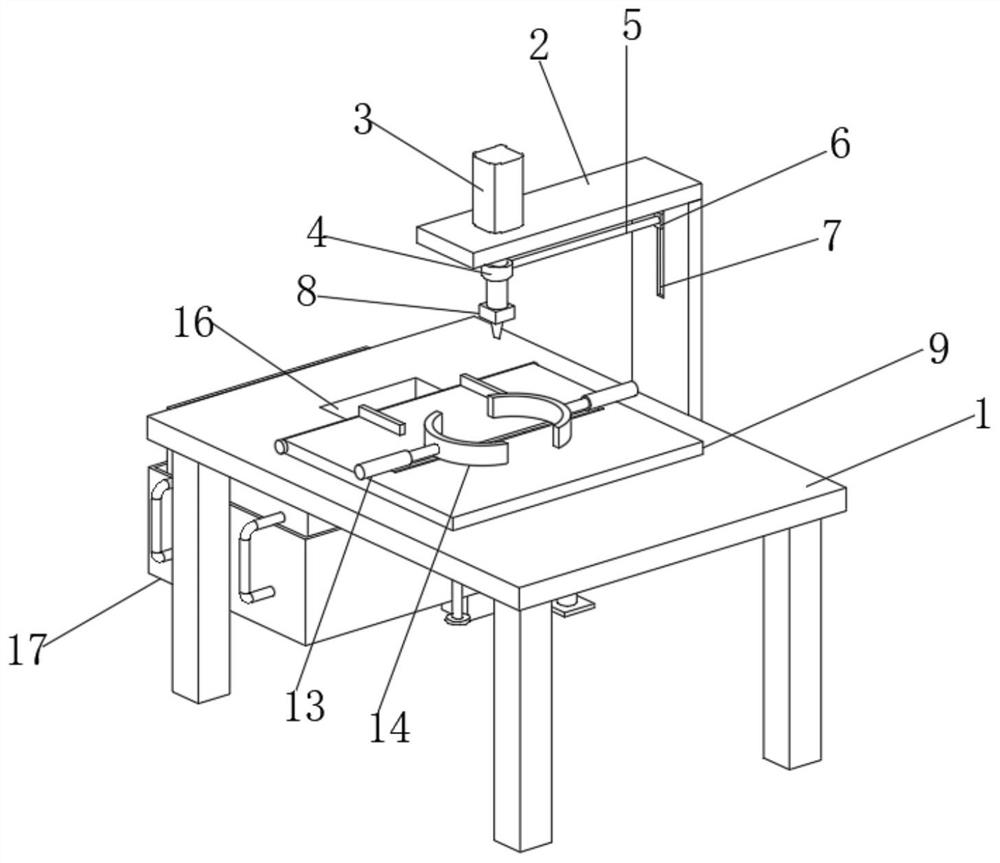
[0031] see Figure 1-3 , the present invention provides a technical solution: a linear motor stator processing and production forming device, including an operating frame 1, the top outer wall of the operating frame 1 is fixedly connected with a mounting frame 2, and the top outer wall of the mounting frame 2 is fixedly connected with a cylinder 3, The outer wall of the cylinder 3 is sleeved with a sleeve block 4, the outer wall of one side of the sleeve block 4 is fixedly connected with a connecting rod 5, the end of the connecting rod 5 away from the sleeve block 4 is fixedly connected with a first slider 6, and the outer wall of one side of the mounting frame 2 There is a first chute 7, the outer wall of the first slider 6 is slidingly connected with the inner wall of the first chute 7, one end of the cylinder 3 is fixedly connected with a stamping device 8, and the top outer wall of the operation frame 1 is movably connected with a processing console 9 The outer wall of th...

Embodiment 2

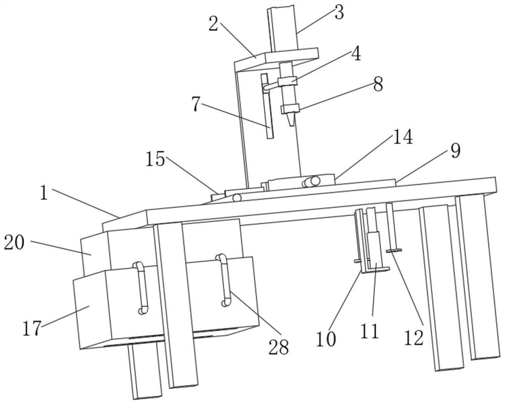
[0034] see Figure 4-7 As shown, on the basis of Embodiment 1, the present invention provides a technical solution: the inner wall of the operating frame 1 is provided with a feeding opening 16, and the top outer wall of the processing operation table 9 close to the feeding opening 16 is fixedly connected with a limit block 15, The outer wall of the bottom of the operating frame 1 is fixedly connected with a support column, and a waste box 17 is arranged between the outer walls of the support column. Block 19, the inner wall of the waste box 17 is provided with a receiving box 20, the outer walls of both sides of the receiving box 20 are fixedly connected with the outer wall of the second slide block 19 away from the second chute 18, and the inner wall of the receiving box 20 is provided with a material box 21 One side inner wall of the material box 21 is movably connected with an inclined plate 22, and the inclined plate 22 is arranged in an array with the vertical direction ...

Embodiment 3

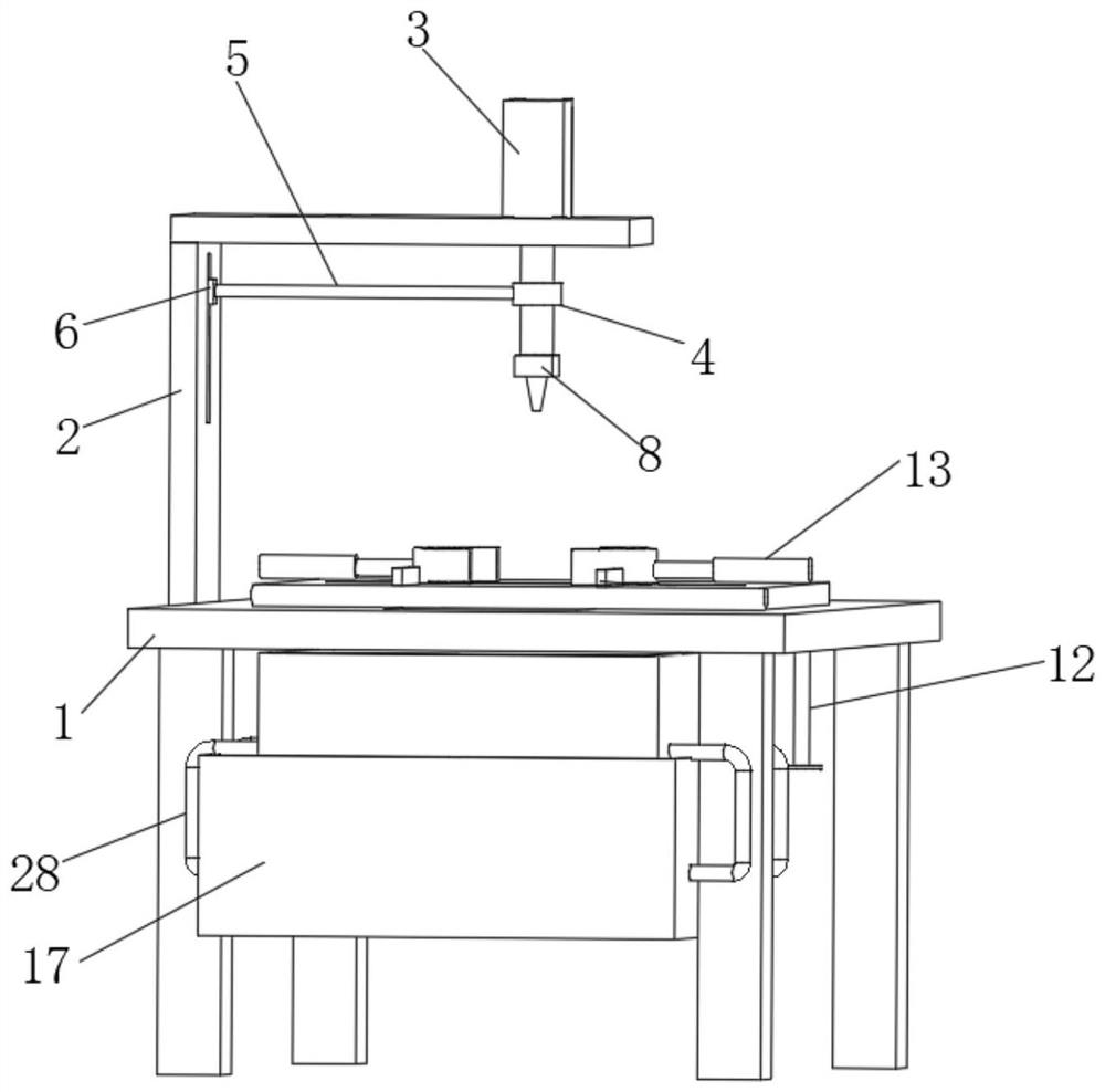
[0037] see Figure 8-9 As shown, on the basis of Embodiment 1 and Embodiment 2, the present invention provides a technical solution: the bottom of the inner wall of the waste box 17 is fixedly connected with an air bag 25, and the inner wall of the air bag 25 is fixedly connected with a rebound sponge 26, and the rebound sponge 26 A second spring 27 is fixedly connected between the outer walls of the airbag 25, and a delivery tube 28 is fixedly connected to the inner wall of the airbag 25. The end of the delivery tube 28 away from the airbag 25 is interspersed and arranged inside the receiving box 20 and the material box 21, and the delivery tube 28 is far away from the airbag 25. One end of the nozzle is fixedly connected with a nozzle 29, and the outer wall of the bottom of the receiving box 20 and the material box 21 is provided with a dust outlet 30.

[0038] In this embodiment, the dust generated by stamping falls into the material box 21 together with the inclination of ...


PUM


Abstract

The invention discloses a forming device for linear motor stator processing production, and relates to the technical field of stator processing. The forming device for the linear motor stator processing and production comprises an operation frame, the outer wall of the top of the operation frame is fixedly connected with a mounting frame, the outer wall of the top of the mounting frame is fixedly connected with an air cylinder, the outer wall of the air cylinder is sleeved with a sleeve block, the outer wall of one side of the sleeve block is fixedly connected with a connecting rod, one end of the air cylinder is fixedly connected with a stamping device, and the outer wall of the top of the operation frame is movably connected with a processing operation table. According to the forming device for the linear motor stator processing and production provided by the invention, inclined plates are used for bearing stators, the stepped inclined plates are used for bearing the stators successively, and when materials in a material box are gradually increased, the materials enable the inclined plates to move towards the inner wall of the material box, so that the situation that the inclined plates occupy much space is avoided, the processed stators are conveniently collected, and the descending speed of the stators is controlled through a friction speed reduction device, so that the stators are prevented from being damaged due to fast descending.

Description

technical field [0001] The invention relates to the technical field of stator processing, in particular to a forming device for linear motor stator processing and production. Background technique [0002] Linear motor is a transmission device that directly converts electrical energy into linear motion mechanical energy without any intermediate conversion mechanism. It can be regarded as a rotating motor cut radially and developed into a plane. Linear motors are also called linear motors, linear motors, linear motors, and push rod motors. The most commonly used types of linear motors are plate and U-groove, and tube. The typical composition of the coil is three-phase, and the brushless commutation is realized by the Hall element. Stamping forming refers to the process of applying external force to plates, strips, pipes and profiles by presses and molds to cause plastic deformation or separation, so as to obtain workpieces (stamping parts) of required shape and size. In th...

Claims


Application Information

Patent Timeline
Patent Type & Authority Applications(China)
IPC IPC(8): B21D22/02B21D43/00B21D43/20B08B5/02H02K15/02
CPCB21D22/02B21D43/003B21D43/20B08B5/02H02K15/02
Inventor 杨振强
Owner 深圳市森克威尔自动化有限公司
Why Eureka
Try Eureka